Ultimate Guide to Chip Resistors: Types, Specifications, and Applications
Chip resistors, the unsung heroes of modern electronics, are tiny components crucial to countless devices around us. From the smartphones in our pockets to the complex machinery in factories, these surface mount devices (SMD) regulate current and voltage with precision. This article dives deep into chip resistors, exploring their structure, function, types, and how they are selected for different applications. Understanding chip resistors is essential to appreciating how electronic circuits function in our digital world, and we will help you gain a solid understanding of this ubiquitous electronic component.
What is a Chip Resistor?
A chip resistor, also known as a surface mount resistor or SMD resistor, is a fundamental passive electronic component designed to limit electrical current and control voltage within a circuit. These small, rectangular components are integral to virtually all modern electronic devices, from smartphones to industrial control systems, providing precise resistance values and enabling accurate circuit behavior.
Chip Resistor Structure and Manufacturing
Chip resistors, fundamental components in modern electronics, are meticulously crafted devices designed to provide precise electrical resistance within compact dimensions. Their construction and manufacturing processes involve a series of intricate steps, employing advanced materials and techniques to achieve the desired performance characteristics.
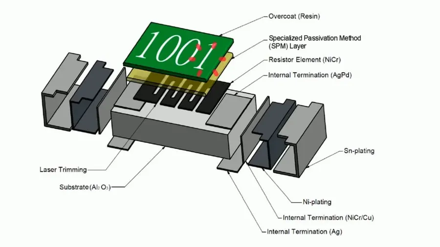
The core structure of a typical chip resistor consists of a resistive element, which is the primary component determining the resistor's electrical properties. This element is generally a thin film or a thick film, made of materials like metal alloys, metal oxides, or carbon-based compounds. The resistive element is supported by a substrate, which serves as the base of the resistor. Typically this is made of ceramic, providing mechanical strength and electrical insulation.
Manufacturing begins with the application of the resistive material onto the substrate. The material deposition method will vary based on the resistor type, ranging from sputtering and evaporation for thin films to screen printing for thick films. After deposition, the resistive material undergoes processes like photolithography or laser etching to pattern and shape the resistive element, defining the effective conductive pathway and therefore the resistance. This process can be done with extreme precision to ensure the accuracy of the specified resistance.
To complete the construction, conductive terminations (usually made of metal, like nickel and tin, applied via a variety of plating or deposition methods) are attached to either end of the resistive element to allow the resistor to be connected into a circuit board. The assembly is finished off with an overcoat to protect the device from the environment and provide electrical insulation. A crucial final manufacturing step is laser trimming. Lasers are used to carefully adjust the effective width of the resistive path to bring the resistor within its desired value and tolerance.
Types of Chip Resistors
Chip resistors are categorized based on their construction and materials, influencing their performance characteristics and suitability for different applications. The primary types include thick film, thin film, and metal film resistors, each offering unique advantages and limitations.
| Type | Construction | Resistance Range | Tolerance | Temperature Coefficient | Typical Applications | Advantages | Disadvantages |
|---|---|---|---|---|---|---|---|
| Thick Film | A paste of conductive material and glass frit is screen-printed onto a ceramic substrate and then fired. | Wide, from ohms to megaohms | Typically 1% to 5% | Moderate, around ±200 ppm/°C | General purpose, cost-sensitive consumer electronics, power supplies | Cost-effective, wide resistance range, robust | Lower precision, higher temperature coefficient, less stable over time |
| Thin Film | A thin layer of metal alloy is sputtered onto a substrate and then patterned. | Moderate, from ohms to tens of kilohms | Typically 0.1% to 1% | Low, around ±25 ppm/°C to ±50 ppm/°C | Precision applications, instrumentation, signal processing, medical devices | High precision and stability, low temperature coefficient | More expensive than thick film, limited resistance range, can be more susceptible to damage |
| Metal Film | Similar to thin film but uses a different metallic composition, often a metal alloy or metal nitride. | Moderate, from ohms to tens of kilohms | Typically 0.1% to 1% | Low, around ±25 ppm/°C to ±100 ppm/°C | High precision, audio equipment, precision instrumentation, RF circuits | High precision and stability, low temperature coefficient, good noise performance | More expensive than thick film, may be more sensitive to high voltage surge, limited resistance range |
Understanding Chip Resistor Markings and Values
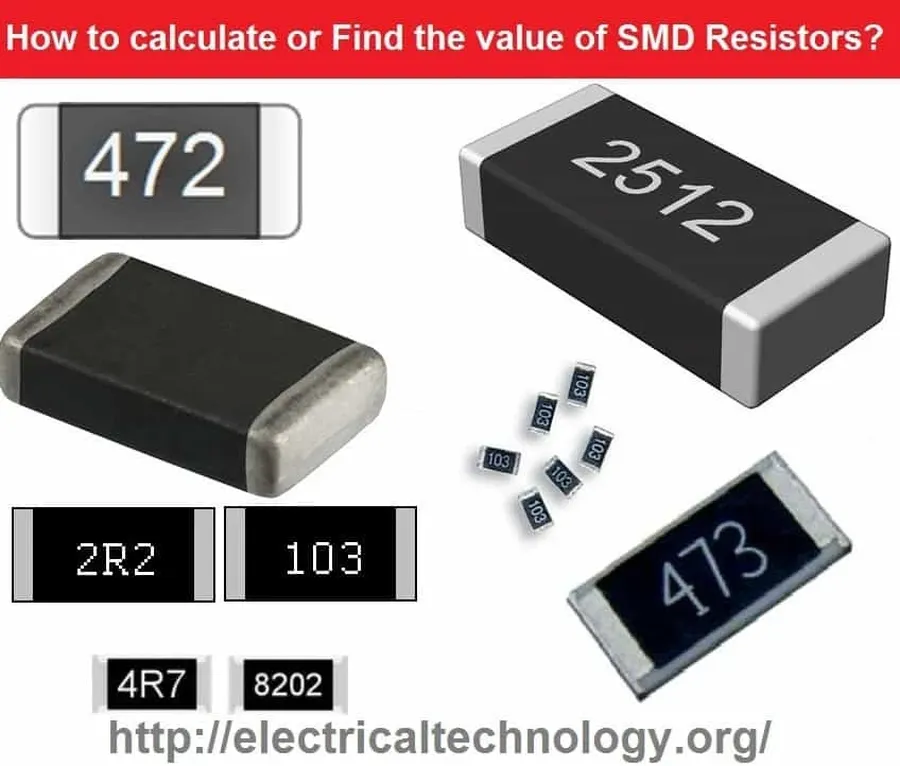
Deciphering the markings on chip resistors is crucial for identifying their resistance value, tolerance, and temperature coefficient. These compact components employ standardized coding systems due to their small size. This section provides a guide to understanding these codes, enabling accurate selection and use in electronic circuits.
| Marking Type | Description | Example | Calculation |
|---|---|---|---|
| 3-Digit Code | First two digits are the significant figures; the third is the multiplier (power of 10). | 103 | 10 * 10^3 = 10,000 Ω (10 kΩ) |
| 4-Digit Code | First three digits are the significant figures; the fourth is the multiplier (power of 10). | 1002 | 100 * 10^2 = 10,000 Ω (10 kΩ) |
| EIA-96 System | A 3-character code where the first two are a numerical code, corresponding to a three-digit value from the EIA-96 table, and the third is a letter multiplier. | 01C | 100 * 10^2 = 10,000 Ω (10 kΩ) |
| Letter Multiplier (EIA-96) | Letters are used to denote multipliers, typically from 10^-2 to 10^2. | A= 10^-2, B=10^-1, C= 1, D=10^1, E=10^2 | Refer to the EIA-96 table for corresponding multipliers. |
| Tolerance Codes | Letters indicating the resistance tolerance. | F=±1%, G=±2%, J=±5%, K=±10% | Value of actual resistance will be in this tolerance band. |
Key Specifications of Chip Resistors
Understanding the key specifications of chip resistors is crucial for selecting the correct component for any electronic circuit design. These specifications define the resistor's performance, reliability, and suitability for various applications. The primary specifications include resistance value, power rating, tolerance, temperature coefficient of resistance (TCR), and operating temperature range.
| Specification | Description | Importance |
|---|---|---|
| Resistance Value | The measure of opposition to current flow, typically measured in ohms (Ω). | Determines circuit behavior; incorrect value can cause malfunctions. |
| Power Rating | The maximum power a resistor can dissipate without damage, measured in watts (W). | Essential to prevent resistor burnout; exceeding rating can lead to failure. |
| Tolerance | The maximum permissible deviation from the stated resistance value, expressed as a percentage (%). | Indicates accuracy of resistance; tight tolerances are needed for precision circuits. |
| Temperature Coefficient of Resistance (TCR) | Describes the change in resistance value per degree Celsius (°C), typically in ppm/°C. | Affects resistor performance with temperature change; critical in high temp environments. |
| Operating Temperature Range | The temperature range over which the resistor can function reliably, specified in °C. | Ensures stability of performance within a range of environmental temperatures. |
Chip Resistor Sizes and Packages
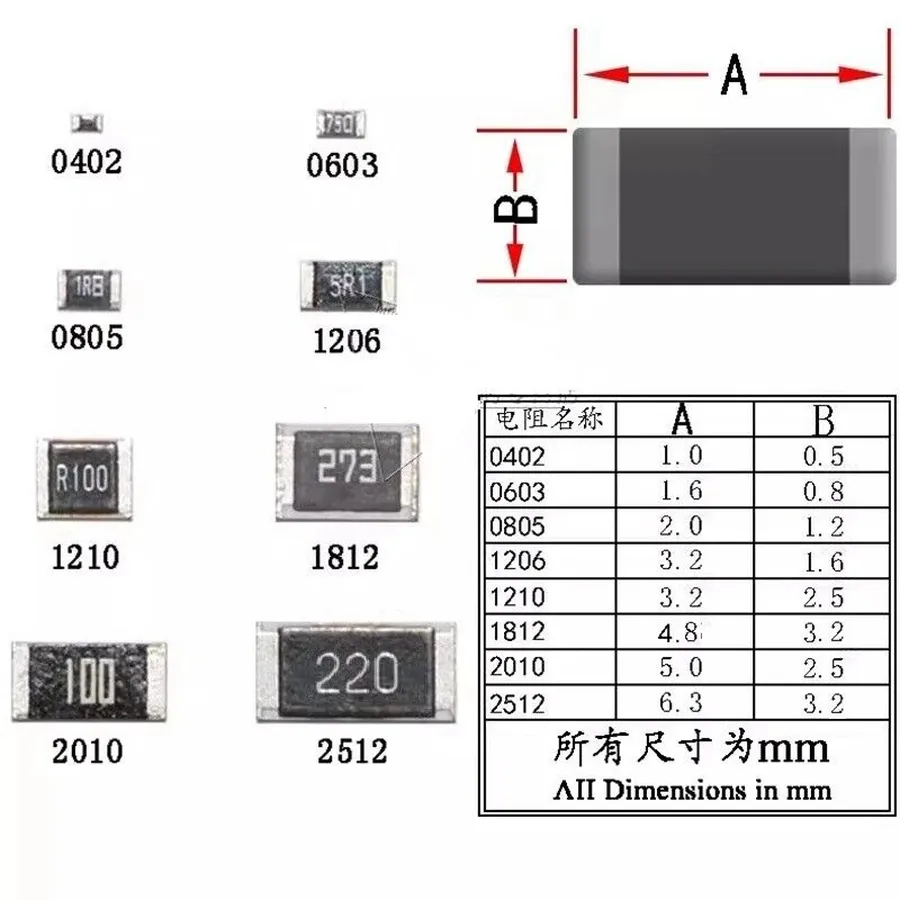
Chip resistor sizes and packages are standardized to ensure compatibility and ease of use in automated manufacturing processes. These dimensions directly influence the power handling capability of the resistor and the amount of board space it occupies. Understanding these standards is crucial for efficient circuit design and assembly.
| Package Size Code (Imperial) | Length (mm) | Width (mm) | Typical Power Rating (W) |
|---|---|---|---|
| 0201 | 0.6 | 0.3 | 1/20 (0.05) |
| 0402 | 1.0 | 0.5 | 1/16 (0.0625) |
| 0603 | 1.6 | 0.8 | 1/10 (0.1) |
| 0805 | 2.0 | 1.25 | 1/8 (0.125) |
| 1206 | 3.2 | 1.6 | 1/4 (0.25) |
| 1210 | 3.2 | 2.5 | 1/3 (0.33) |
| 2010 | 5.0 | 2.5 | 3/4 (0.75) |
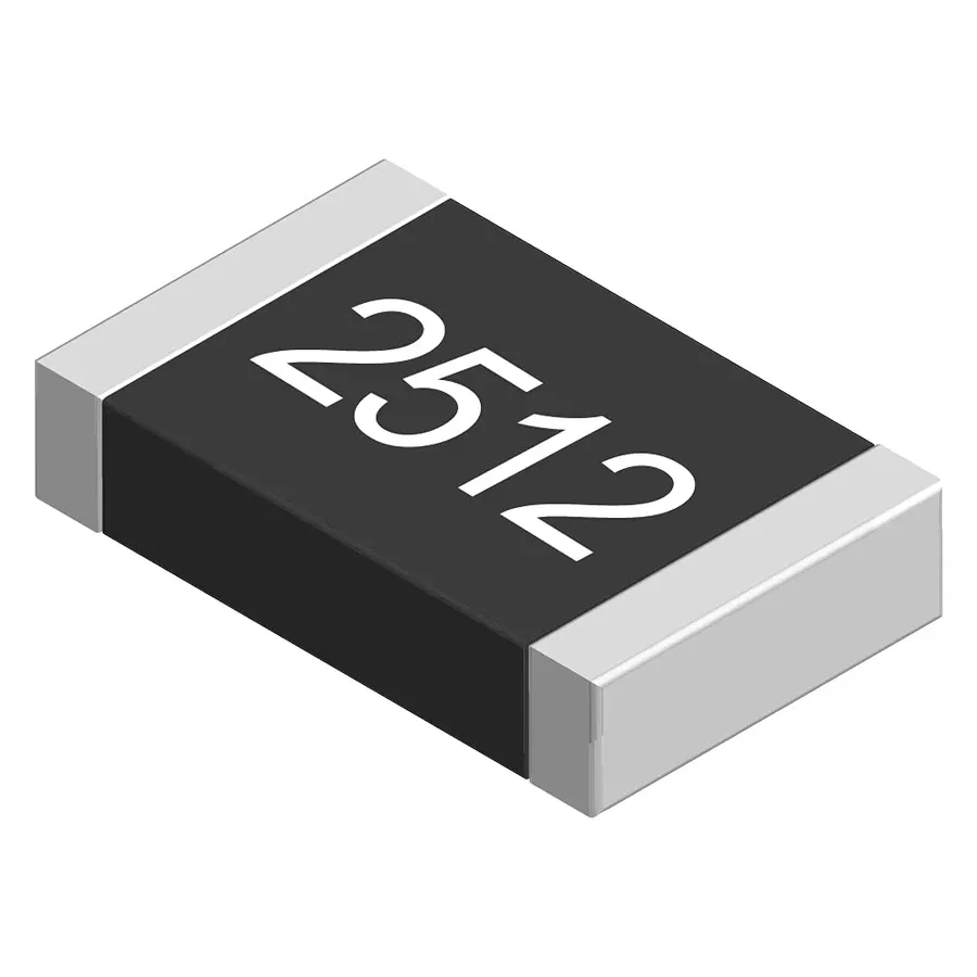
| 2512 | 6.3 | 3.2 | 1 (1.0) |
The package size code, often represented in imperial units (e.g., 0402, 0603), directly corresponds to the physical dimensions of the resistor. For instance, a '0603' resistor measures 0.06 inches in length and 0.03 inches in width, while a '1206' resistor measures 0.12 inches in length and 0.06 inches in width. Choosing the correct package size involves considering both the power dissipation requirements of the circuit and the available space on the PCB.
It's important to note that while the table provides typical power ratings, these values can vary slightly between manufacturers. Always refer to the specific datasheet of the resistor being used to determine its exact power rating and other critical parameters.
Selecting the Right Chip Resistor for Your Application
Selecting the appropriate chip resistor is crucial for the reliable operation of any electronic circuit. This process involves carefully considering several key factors to ensure the chosen component meets the specific demands of the application. Over-specification can lead to unnecessary costs and size constraints, while under-specification may result in component failure and circuit malfunction. Thus, matching the resistor's characteristics with the circuit requirements is essential for optimal performance and longevity.
- Power Dissipation
The resistor's power rating must exceed the actual power it will dissipate in the circuit. Calculate power dissipation using P = I²R (where P is power, I is current, and R is resistance) or P = V²/R (where V is voltage). Always choose a resistor with a power rating that provides a safety margin, typically 25% or more above the expected dissipation. - Resistance Value
The resistance value should match the design requirements of the circuit. Consider the circuit's function and choose a resistor within the necessary tolerance to achieve the desired voltage or current. Be aware of the effects of tolerance accumulation in circuits containing multiple resistors. - Tolerance
Tolerance specifies the acceptable range of deviation from the nominal resistance value. Choose a tolerance that aligns with your circuit's precision needs. Precision circuits might need 0.1% or 0.5% tolerance, while general applications may be suitable with 1% or 5%. - Temperature Coefficient of Resistance (TCR)
TCR indicates how much the resistance changes with temperature. High-precision applications require resistors with low TCRs to minimize resistance variation due to temperature fluctuations. Consider the operating temperature range of your application and select accordingly. Different materials exhibit different TCR characteristics. - Environmental Conditions
Select resistors rated for the intended operating environment, considering temperature, humidity, and potential exposure to corrosive substances. High-temperature applications may require resistors with specialized materials or packaging. Also, ensure your chosen resistor's storage and operating temperatures are appropriate. - Physical Size and Package
The physical size and package of the resistor should fit the circuit board and meet space constraints, while also considering power requirements. Common sizes such as 0402, 0603, 0805, and 1206 have different power ratings and footprint dimensions. For space-constrained designs, smaller resistors with lower power handling can be used, while in power-intensive applications, larger resistors with sufficient heat dissipation capability are necessary. - Stability
The resistor's long-term stability is important, especially for applications requiring consistent performance. Choose resistors with low drift rates over time to ensure stable circuit operation. Film resistors tend to exhibit better long-term stability than other types.
Chip Resistor Applications Across Industries
Chip resistors are ubiquitous components across diverse industries, serving as fundamental elements in electronic circuits for current limiting, voltage control, and signal conditioning. Their small size, reliability, and wide range of available values make them essential for a vast array of applications.
Here's an overview of their prominent uses:
- Consumer Electronics
Chip resistors are extensively used in smartphones, tablets, laptops, digital cameras, televisions, and audio equipment. They are critical for ensuring precise voltage and current control within the circuits of these devices. - Automotive
In the automotive sector, chip resistors are found in various control systems including engine management, anti-lock braking (ABS), airbag deployment, and infotainment systems. Their resilience to temperature variations and mechanical stress is key for automotive applications. - Industrial Automation
Chip resistors play an essential role in industrial control systems, power supplies, motor drives, and sensor circuits. They contribute to reliable and efficient operation in harsh industrial environments. - Medical Devices
Medical applications include monitoring equipment, diagnostic tools, imaging systems, and implantable devices. The high precision and reliability of chip resistors are crucial in such sensitive applications. - Aerospace and Military
Chip resistors used in aerospace and military applications must meet rigorous standards for reliability and performance. They're used in navigation systems, communication equipment, and control systems where precision is paramount. - Telecommunications
Chip resistors are foundational in telecommunications equipment, including base stations, routers, switches, and networking devices. They provide precise control of signal levels, ensuring reliable communication links. - Renewable Energy Systems
Chip resistors are used in solar inverters, wind turbine controllers, and other renewable energy systems. They are vital for precise power control and efficient energy conversion.
Frequently Asked Questions About Chip Resistors
This section addresses frequently asked questions about chip resistors, aiming to clarify common doubts regarding their functionality, identification, and specific types. We will cover topics ranging from reading their values to understanding their limitations and special configurations like flip-chip resistors.
- What is a chip resistor?
A chip resistor is a surface-mount passive component designed to impede the flow of electrical current within a circuit. These small, rectangular devices are crucial for controlling voltage levels and establishing proper circuit behavior. They are manufactured by depositing a resistive material on a ceramic substrate, with terminations for soldering to the circuit board. - How do you read the value of a chip resistor?
Reading chip resistor values depends on the marking system used. Some resistors use a three or four-digit numerical code where the first digits represent the value and the last digit represents the multiplier (e.g., '103' means 10 x 10^3 ohms or 10k ohms). Other resistors may use an EIA-96 code which requires decoding. For precise understanding refer to the manufacturer's datasheet or use a digital multimeter to measure the resistance directly. - Do microchips have built-in resistors?
Microchips, or integrated circuits, often do contain resistors as part of their internal circuitry. These are usually very small and made using thin-film processes, serving specific functions within the chip. However, these internal resistors are not the same as discrete chip resistors that are surface-mounted on the circuit board. - What is a flip chip resistor?
A flip-chip resistor is a type of surface mount resistor designed for direct connection onto a PCB. Instead of having terminations on the sides, the terminations are on the bottom. These are mounted upside down onto the board, and are often smaller and offer improved thermal performance compared to standard chip resistors. This mounting style minimizes inductance, making them particularly useful in high-frequency applications. - What is the difference between a thick film and a thin film chip resistor?
Thick film resistors are manufactured by screen-printing a layer of resistive paste onto the substrate, which is then fired, this method is cost effective for mass production but offer lower precision and tolerances compared to thin film resistors. Thin film resistors use advanced vacuum deposition techniques to create a very thin, precise layer of resistive material on a ceramic substrate, thin film provide much higher accuracy, better temperature stability and lower noise, making them suitable for demanding applications. - What are the typical tolerances for chip resistors?
Chip resistor tolerances can vary widely depending on the resistor type and intended application. Typical tolerances range from ±0.1% for high-precision thin-film resistors to ±5% or ±10% for general-purpose thick-film resistors. It is crucial to select a resistor with appropriate tolerance to meet circuit performance requirements. - Can I use a higher wattage rated chip resistor?
Yes, in most cases, you can use a chip resistor with a higher power rating than required. Using a higher power rated resistor is not harmful and provides a safety margin against heat build up. However, you should not use a resistor with a lower power rating, as that could lead to failure due to overheating.
Chip Resistor Comparison Table
To facilitate informed decision-making, the following table provides a comprehensive comparison of different chip resistor types, outlining their key characteristics, advantages, and disadvantages.
| Feature | Thick Film | Thin Film | Metal Film |
|---|---|---|---|
| Resistance Range | Wide (1Ω - 100MΩ) | Moderate (10Ω - 1MΩ) | Moderate (1Ω - 1MΩ) |
| Tolerance | Typically ±1% to ±5% | Typically ±0.1% to ±1% | Typically ±0.1% to ±1% |
| Temperature Coefficient (TCR) | Moderate (+/- 100 to +/- 250 ppm/°C) | Low (+/- 25 to +/- 100 ppm/°C) | Low (+/- 25 to +/- 100 ppm/°C) |
| Power Rating | Moderate | Moderate to low | Moderate to low |
| Stability | Good | Excellent | Excellent |
| Cost | Low | Moderate | Moderate |
| Precision | Moderate | High | High |
| Applications | General-purpose applications, consumer electronics. | Precision circuitry, medical devices, audio equipment. | Precision circuitry, high-stability applications. |
| Advantages | Cost-effective, versatile resistance range. | High precision, low TCR, good stability. | High precision, low TCR, good stability. |
| Disadvantages | Lower precision, higher TCR. | Higher cost, limited power rating. | Higher cost, limited power rating. |
Chip resistors, though small, play an immense role in enabling the functionality of electronic devices. By understanding their types, specifications, and applications, engineers and enthusiasts can select the right components for their projects. The continued advancements in chip resistor technology allow for even greater efficiency and precision in the future of electronics, ensuring these tiny components remain vital for years to come. Choosing the right chip resistor is the first step for building any functional circuit, and a better understanding of chip resistors can bring you one step closer to better electronic solutions.