Understanding Circuit Resistors: Types, Functions, and Applications
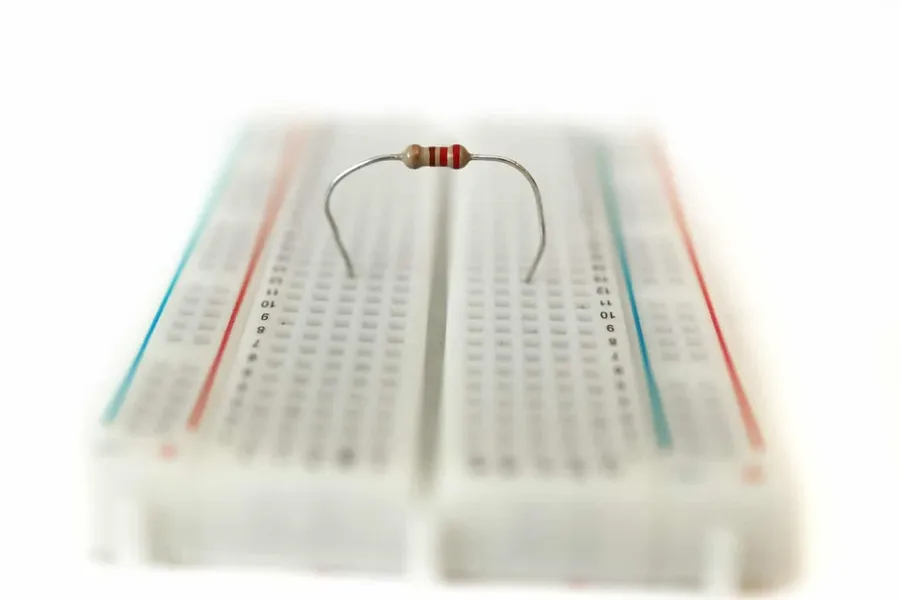
In our interconnected world, electronic circuits are the backbone of countless devices, from smartphones to advanced medical equipment. At the heart of these circuits are components like the circuit resistor, acting as the unsung hero, controlling electrical flow, just like a valve regulates water pressure in pipes. This article will delve deep into understanding circuit resistors – their purpose, types, applications, and more, demystifying these crucial components.
What is a Circuit Resistor?
A circuit resistor is a fundamental passive electrical component engineered to oppose the flow of electrical current within a circuit. This opposition, known as resistance, is quantified in ohms (Ω) and is crucial for controlling current levels, attenuating voltage, and ensuring proper circuit operation. Resistors achieve this by converting electrical energy into heat, a process known as Joule heating.
How Resistors Work: The Basics of Resistance

At the core of every circuit resistor lies the fundamental principle of electrical resistance, which is the opposition to the flow of electric current. This opposition, measured in ohms (Ω), is not merely an obstruction but a crucial property that allows us to manipulate and control electrical circuits. The behavior of a resistor is elegantly described by Ohm's Law, V = IR, which states that the voltage (V) across a resistor is directly proportional to the current (I) flowing through it and the resistance (R) of the resistor.
Understanding how resistance affects current is vital for circuit design. A higher resistance will result in a lower current for a given voltage, and vice versa. This capability to control current makes resistors indispensable for numerous electronic applications. When a voltage is applied across a resistor, the electrical energy is converted into heat due to collisions between charge carriers and the material of the resistor, this is called the Joule effect, the effect is especially apparent when the electrical current and resistance are high. The heat that generated dissipates into the environment.
| Concept | Description | Units |
|---|---|---|
| Resistance (R) | The opposition to current flow. | Ohms (Ω) |
| Current (I) | The flow of electrical charge. | Amperes (A) |
| Voltage (V) | The electrical potential difference. | Volts (V) |
| Ohm's Law | V = IR, voltage equals current times resistance | N/A |
The relationship between voltage, current and resistance is fundamental to understanding circuit behavior. The resistance of a resistor depends on several factors such as its material, length and cross-sectional area. Materials that have high resistance, are called insulators, materials with low resistance are called conductors, and resistors are specifically designed to exhibit a controlled amount of resistance between these two extremes. In essence, the resistor is a fundamental control device in an electronic circuit.
Types of Resistors: A Comprehensive Overview
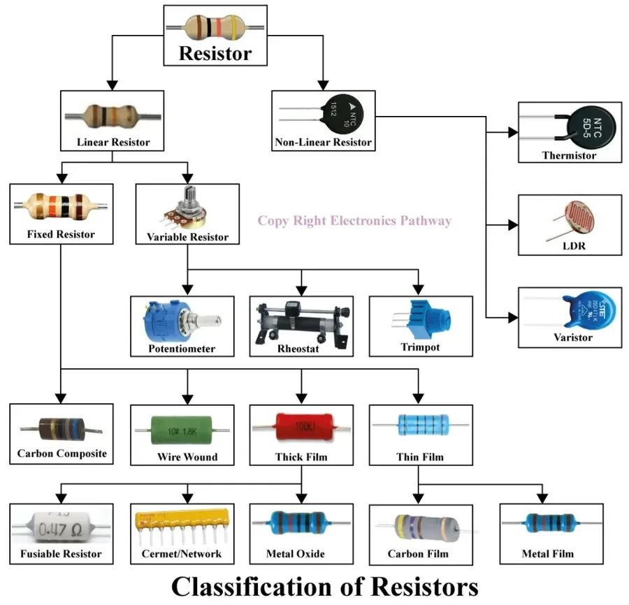
Circuit resistors are diverse components, each designed with unique characteristics to meet specific application needs. These can be broadly categorized into fixed resistors, variable resistors, and specialized resistors, each offering distinct functionalities in electronic circuits.
| Resistor Type | Description | Typical Applications | Advantages | Disadvantages |
|---|---|---|---|---|
| Fixed Resistors | Provide a constant resistance value that is set during manufacturing. | General circuits, current limiting, voltage division. | Low cost, widely available, reliable. | Resistance value cannot be changed, less precise. |
| Carbon Film | A thin carbon film is deposited on a ceramic substrate. | General-purpose circuits. | Inexpensive, good for general use. | High temperature sensitivity, less precise than metal film. |
| Metal Film | Thin metal film deposited on a ceramic substrate. | Precision circuits, high-accuracy applications. | High precision, low temperature coefficient, low noise. | More expensive than carbon film resistors. |
| Wire-Wound | Made by winding a resistance wire around an insulating core. | High-power applications, precision circuits. | High power handling capability, high precision. | Inductive, higher cost, larger size. |
| Variable Resistors | Allow for the adjustment of resistance. | Adjustable circuits, volume controls, tuning. | Adjustable resistance value. | Less stable than fixed resistors, potential for mechanical wear. |
| Potentiometers | Three terminals and a rotating or sliding contact. | Voltage division, user-adjustable settings. | Versatile for voltage control. | Limited power rating, less precise. |
| Rheostats | Two terminals and a sliding contact. | Current control, motor speed adjustments. | Can handle higher currents than potentiometers. | Limited variability, may not be as precise. |
| Specialized Resistors | Have specific properties based on environmental conditions. | Temperature or light-sensitive circuits. | Respond to specific environmental factors. | Performance is tied to the specific parameter they respond to. |
| Thermistors | Resistance changes with temperature. | Temperature sensing, thermal compensation. | High temperature sensitivity. | Non-linear response, limited temperature range. |
| Photoresistors | Resistance changes with light intensity. | Light sensing, automated lighting control. | High sensitivity to light. | Response time may be slow, not highly stable. |
Resistor Color Codes and Markings
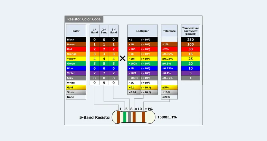
Resistor color codes and markings provide a standardized method for indicating the resistance value and tolerance of a resistor. Understanding these codes is essential for accurately identifying and using resistors in circuit design and repair. These markings use a system of colored bands or alphanumeric codes, allowing for quick and efficient identification of resistor specifications.
| Band | Color | Digit Value | Multiplier | Tolerance |
|---|---|---|---|---|
| 1st Band | Black | 0 | N/A | N/A |
| 1st Band | Brown | 1 | 10^1 | ±1% |
| 1st Band | Red | 2 | 10^2 | ±2% |
| 1st Band | Orange | 3 | 10^3 | N/A |
| 1st Band | Yellow | 4 | 10^4 | N/A |
| 1st Band | Green | 5 | 10^5 | ±0.5% |
| 1st Band | Blue | 6 | 10^6 | ±0.25% |
| 1st Band | Violet | 7 | 10^7 | ±0.1% |
| 1st Band | Grey | 8 | 10^8 | ±0.05% |
| 1st Band | White | 9 | N/A | N/A |
| Multiplier | Gold | N/A | 10^-1 | ±5% |
| Multiplier | Silver | N/A | 10^-2 | ±10% |
| Tolerance | None | N/A | N/A | ±20% |
For a typical 4-band resistor, the first two bands represent the first two digits of the resistance value, the third band is the multiplier, and the fourth is the tolerance. A 5-band resistor adds a third significant digit, increasing precision. Some resistors also include a sixth band to indicate temperature coefficient.
Understanding how to decode these color bands correctly is crucial for selecting the right resistor for a specific application, avoiding any misinterpretations that could lead to circuit malfunctions or damage. Always double check your readings and refer to reliable resources when interpreting resistor values.
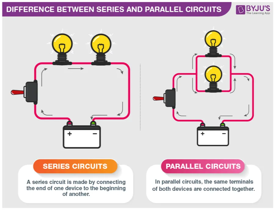
Resistors in Series and Parallel Circuits
Understanding how resistors behave in series and parallel configurations is fundamental to circuit analysis and design. The arrangement of resistors significantly impacts the overall resistance and current flow within a circuit, requiring distinct calculation methods for each configuration.
| Characteristic | Series Circuits | Parallel Circuits |
|---|---|---|
| Current Flow | Same through all resistors | Divides among branches |
| Voltage | Divides across resistors | Same across all resistors |
| Total Resistance (RT) | RT = R1 + R2 + R3 + ... | 1/RT = 1/R1 + 1/R2 + 1/R3 + ... |
| Calculation | Simple addition of resistance values. | Reciprocal of the sum of reciprocals of resistance values. |
In series circuits, resistors are connected end-to-end, forming a single path for current flow. The total resistance is simply the sum of individual resistances. Conversely, in parallel circuits, resistors are connected side-by-side, providing multiple paths for current. The total resistance in parallel is always less than the smallest individual resistance and requires a different formula calculation.
These configurations are crucial in circuit design as they allow engineers to manipulate current and voltage levels, tailoring the circuit to meet specific application needs. For instance, resistors in series can be used to limit current, while resistors in parallel can be used to divide current among different paths.
Diagrammatically, a series circuit shows components connected one after another along a single line, while a parallel circuit demonstrates components with their ends connected to the same nodes, creating branches.
Common Applications of Circuit Resistors
Circuit resistors are ubiquitous in electronics, performing essential functions that ensure proper operation and protection of various circuits. They are not merely passive components, but rather active elements in controlling current, voltage, and signal integrity. Their widespread use stems from their ability to precisely manage electrical parameters, which is crucial for the stability and reliability of electronic systems. This section will explore key applications of resistors in real-world scenarios, supported by specific examples.
Resistors are pivotal in several key applications, broadly categorized as current limiting, voltage division, signal biasing, and impedance matching. These applications showcase how resistors actively shape the behavior of electrical circuits to achieve the desired functionalities. Each use case emphasizes different aspects of resistive behavior and its importance.
- Current Limiting
Resistors are crucial for limiting current to protect sensitive components, such as LEDs and microcontrollers. By placing a resistor in series, the current can be controlled to prevent overcurrent damage. For example, in an LED circuit, a resistor ensures that the LED receives the correct current and does not burn out due to excessive current flow. - Voltage Division
Resistors are used in voltage dividers to create a fraction of the input voltage. This technique is useful for generating reference voltages or for scaling down voltages for use in sensitive measurement circuits. By connecting resistors in series, a specific voltage drop can be achieved across each resistor, enabling the creation of precise voltage outputs. The voltage divider principle is used extensively in sensor circuits and analog signal conditioning. - Signal Biasing
In transistor circuits, resistors are used to establish appropriate operating points, known as bias points. These bias points ensure that transistors are operating in their desired active region, where they can amplify signals effectively without distortion. Precise biasing with resistors is key for amplification circuits found in audio systems and radio frequency communication devices. - Impedance Matching
Resistors play a vital role in impedance matching to maximize power transfer between different stages of a circuit. Matching impedances in transmission lines and amplifiers is essential for minimizing signal reflection and loss. By matching the source and load impedances, maximum power delivery is ensured. This is particularly important in communication systems and high-frequency electronic devices.
| Application | Function | Example Scenario |
|---|---|---|
| Current Limiting | Protect sensitive components by limiting current flow | LED circuit with a series resistor |
| Voltage Division | Generate a specific fraction of the input voltage | Voltage divider in a sensor circuit |
| Signal Biasing | Establish desired operating points for transistors | Transistor amplifier with bias resistors |
| Impedance Matching | Maximize power transfer and reduce signal loss | RF amplifier with matching network |
In summary, resistors are not just simple components but are critical elements that enable control and manipulation of electrical signals within a vast array of electronic applications. These examples highlight the essential role of resistors in ensuring the reliability and performance of electronic circuits.
Frequently Asked Questions About Circuit Resistors
This section addresses common questions about circuit resistors, providing practical answers and insights to enhance understanding for beginners and hobbyists.
- What is the primary function of a circuit resistor?
The core function of a circuit resistor is to impede the flow of electrical current. By doing so, it controls current magnitude, reduces voltage, and influences the overall behavior of the circuit. This control is fundamental in preventing damage to sensitive components and ensuring proper circuit operation. - What are the most common types of circuit resistors?
Common types include fixed resistors (carbon film, metal film, and wire-wound), variable resistors (potentiometers and rheostats), and specialized resistors such as thermistors and photoresistors. Each type is designed for specific applications based on their resistance characteristics, precision, and how they respond to environmental changes or mechanical adjustments. - What happens when you add a resistor into a circuit?
Adding a resistor to a circuit will reduce the current flow in that path of the circuit. This is due to the resistor introducing a specific resistance to the flow of electrons. The magnitude of this current reduction is proportional to the resistance value. As current decreases, the voltage drop across the resistor increases in accordance with Ohm's Law (V=IR). - Does the orientation of a resistor matter in a circuit?
For the majority of standard resistors (fixed resistors), the orientation does not matter. They are non-polar components, meaning they function the same regardless of which direction they are placed in the circuit. However, certain specialized resistors, like some surface-mount devices (SMD), might have specific markings or polarities that need to be considered when installing. - What are the standard symbols for a resistor in circuit diagrams?
In circuit diagrams, a resistor is typically represented by a zigzag line (an older standard) or a rectangle. The rectangle is becoming more common in modern diagrams. The zigzag symbol represents a standard resistor, while variable resistors (potentiometers and rheostats) might have an additional arrow across their symbol, indicating that their resistance can be adjusted. Always verify the circuit diagram's legend for clarity. - Why are resistors used in electronic circuits?
Resistors are essential for numerous reasons. They limit current to protect components, they divide voltage to create specific levels needed for different parts of a circuit, they set up bias points for transistors, they shape the frequency response in filters, and they match impedance to reduce signal reflection, among other tasks. In short, resistors allow us to design circuits with specific operating parameters. - How do I identify the value of a resistor?
The value of most resistors is determined through a color code or numeric markings directly on the resistor body. The color code uses colored bands to represent numbers, multipliers, and tolerance levels. A variety of charts and tools are available online and in electronics resources to decode these bands. Some resistors use numeric codes, especially small surface-mount devices (SMD).
Troubleshooting Common Resistor Problems
Effective troubleshooting of circuit resistors involves diagnosing common issues such as overheating, failures caused by overload, and physical damage. Understanding these failure modes and implementing proper testing techniques are essential for maintaining circuit integrity and reliability.
- Overheating
Resistors can overheat when the power dissipation exceeds their rated capacity. This often leads to visible signs like discoloration, charring, or even melting of the resistor's body. Verify the resistor's power rating and the actual power being dissipated in the circuit using Ohm's law (P=I^2R or P=V^2/R). Excessive current flow is the most common cause. - Open Circuit Failure
An open circuit failure occurs when a resistor completely stops conducting electricity. This is typically due to extreme overheating, physical damage, or manufacturing defects. Use a multimeter set to resistance measurement to confirm if the resistor reads an infinite resistance, indicating it's open circuit. Often, this will be preceded by signs of overheating. - Changed Resistance Value
While not a complete failure, a resistor's value can drift from its specified value over time, temperature, or due to manufacturing variance. Use a multimeter to compare the measured value against its color code or markings. A significant deviation will alter circuit behavior. Consider replacing resistors that have drifted beyond their tolerance levels. - Physical Damage
Resistors can be damaged by physical stress such as bending, impacts, or exposure to corrosive substances. Visible cracks, breaks, or damaged leads indicate a need for replacement. Careful handling is essential to avoid physical damage. - Solder Joint Issues
A seemingly faulty resistor could be due to a poor solder joint. Inspect solder joints for cold solder or cracked solder, and reflow the joint with flux. If the resistance is still incorrect, replace the resistor.
| Symptom | Possible Cause | Troubleshooting Step |
|---|---|---|
| Discoloration or Charring | Overheating due to excessive power dissipation | Check the resistor's power rating and calculate power in the circuit |
| Open circuit (infinite resistance) | Extreme overheating or physical damage | Measure resistance with a multimeter; if open, replace resistor |
| Incorrect resistance value | Value drift, or physical damage | Measure resistance, compare to color codes and markings; replace if outside tolerance |
| Physical cracks or breaks | Physical stress | Replace damaged resistors |
| Intermittent or poor connection | Poor solder joint | Inspect solder joint, reflow and check continuity |
In summary, circuit resistors are fundamental elements in electronic circuits, playing vital roles in managing current flow and enabling various functionalities. Understanding their types, applications, and how they interact within circuits is key to successful electronic design and troubleshooting. As technology evolves, so will the designs and applications of resistors, highlighting their enduring importance in the field of electronics. The ability to control resistance remains a cornerstone of modern electrical engineering and will continue to be important in future innovations.