Understanding Microfarads (µF): A Practical Guide to Capacitance
In the realm of electronics, the microfarad (µF) is a fundamental unit of capacitance, much like the heartbeat of electronic circuits. It's the ability of a component, typically a capacitor, to store an electrical charge. This article delves into the practical world of microfarads, offering clarity on their meaning, usage, and importance, and relating this core electronic concept to both everyday electronics and advanced engineering applications. We’ll cover everything from the basic definition of microfarads to its real world applications, helping you understand what makes this tiny unit a powerhouse of technology.
What is a Microfarad (µF)?
A microfarad (µF) is a unit of capacitance, representing one millionth (10⁻⁶) of a farad (F). It quantifies a capacitor's ability to store electrical charge. The microfarad is a more practical unit for everyday electronics compared to the farad, which represents a very large amount of capacitance.
In the International System of Units (SI), the farad is the base unit of capacitance, named after Michael Faraday. The prefix 'micro' denotes a factor of 10⁻⁶, making a microfarad a derived SI unit. This scaling is crucial for practical electronics, allowing for convenient measurements of capacitor sizes commonly found in circuits.
Microfarads vs. Farads: Understanding the Scale
The farad (F), the base unit of capacitance in the International System of Units (SI), represents a very large amount of capacitance. For practical electronics, the microfarad (µF), which is one millionth of a farad, is much more commonly used due to the smaller values that are typical in circuits. This section will detail the significant difference in scale between these two units, clarifying why microfarads are the go-to unit in most real-world applications, as well as discuss other related units.
| Unit | Symbol | Value in Farads | Typical Use |
|---|---|---|---|
| Farad | F | 1 F | High-capacitance applications, such as energy storage. |
| Millifarad | mF | 10^-3 F | Used infrequently due to the smaller capacitance values generally used in electronics |
| Microfarad | µF | 10^-6 F | Most common unit for electronic circuits, e.g. in power supplies. |
| Nanofarad | nF | 10^-9 F | Common in high-frequency applications, bypass capacitors. |
| Picofarad | pF | 10^-12 F | Used in RF and high-precision circuits; very low capacitance. |
The relationship between farads and microfarads is defined as follows: 1 Farad (F) = 1,000,000 Microfarads (µF), or equivalently, 1 Microfarad (µF) = 0.000001 Farads (F) = 10^-6 F. This conversion is essential for understanding capacitor ratings and is foundational for circuit design and analysis. While the farad is the standard unit, the microfarad is far more practical due to the common range of capacitance values needed in electronic devices. The table above gives other commonly used units of capacitance.
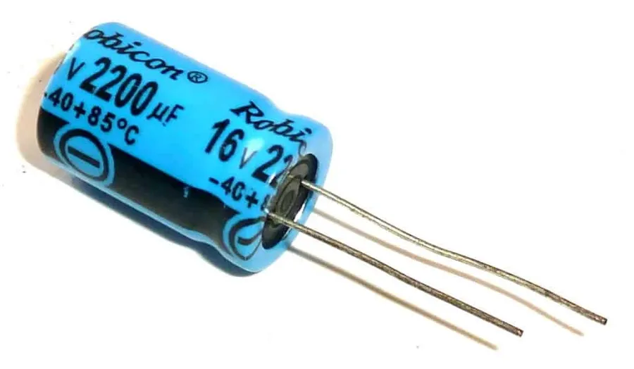
Microfarads in Capacitors: How They Work
Capacitors, essential components in electronic circuits, store electrical energy in an electric field. The ability of a capacitor to store charge is quantified by its capacitance, measured in farads (F). However, due to the farad being a large unit, capacitance is more commonly expressed in microfarads (µF) for practical applications. A capacitor's microfarad rating directly indicates how much charge it can store at a given voltage.
The capacitance of a capacitor is determined by its physical characteristics, primarily the area of the conducting plates, the distance separating them, and the dielectric material between the plates. A larger plate area, a smaller separation, and a higher permittivity of the dielectric all lead to higher capacitance, and hence a greater microfarad value.
| Physical Property | Effect on Capacitance (µF) |
|---|---|
| Plate Area | Larger area increases capacitance |
| Plate Separation | Smaller separation increases capacitance |
| Dielectric Material | Higher permittivity increases capacitance |
The relationship between these factors and capacitance (C) is described by the formula: C = ε(A/d), where 'ε' is the permittivity of the dielectric material, 'A' is the area of the plates, and 'd' is the distance between the plates. This shows that capacitance is directly proportional to the dielectric constant and the plate area, while inversely proportional to the separation distance. Therefore, capacitors with higher µF ratings will typically have larger plate areas, smaller plate separations, or higher permittivity dielectric materials.
In practical terms, a capacitor rated at, say, 10 µF, will store ten times more charge at the same voltage compared to a capacitor rated at 1 µF. This understanding is crucial for circuit design and component selection, ensuring that capacitors meet the storage needs of their intended application.
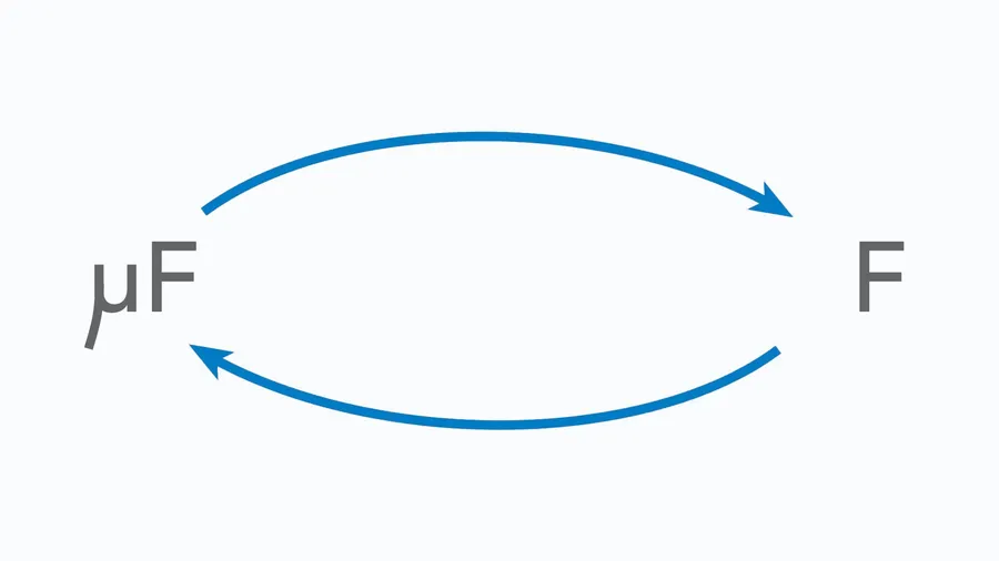
Microfarads to Farads Conversion: Formulas and Examples
Converting between microfarads (μF) and farads (F) is essential for working with capacitors and understanding their capacitance values. This section details the conversion formula and provides practical examples to facilitate a clear understanding of these unit conversions.
The fundamental relationship is that one farad is equal to one million microfarads. This conversion is crucial because farads represent a very large amount of capacitance, whereas microfarads are more commonly encountered in practical electronics.
| Conversion Type | Formula | Example |
|---|---|---|
| Microfarads to Farads | Farads = Microfarads / 1,000,000 | 500 μF = 0.0005 F |
| Farads to Microfarads | Microfarads = Farads * 1,000,000 | 0.002 F = 2000 μF |
It is important to note that when performing these calculations, maintaining correct decimal placement is vital to avoid errors. Understanding the practical implications of these conversions is paramount in real-world applications.
For instance, a capacitor labeled 100 μF indicates a storage capacity of 0.0001 farads. Conversely, if a circuit design specifies a capacitor of 0.001 F, it implies a requirement for a 1000 μF capacitor. Familiarity with these conversions will significantly improve your ability to evaluate and utilize capacitors effectively in diverse applications.
Practical Applications of Microfarads
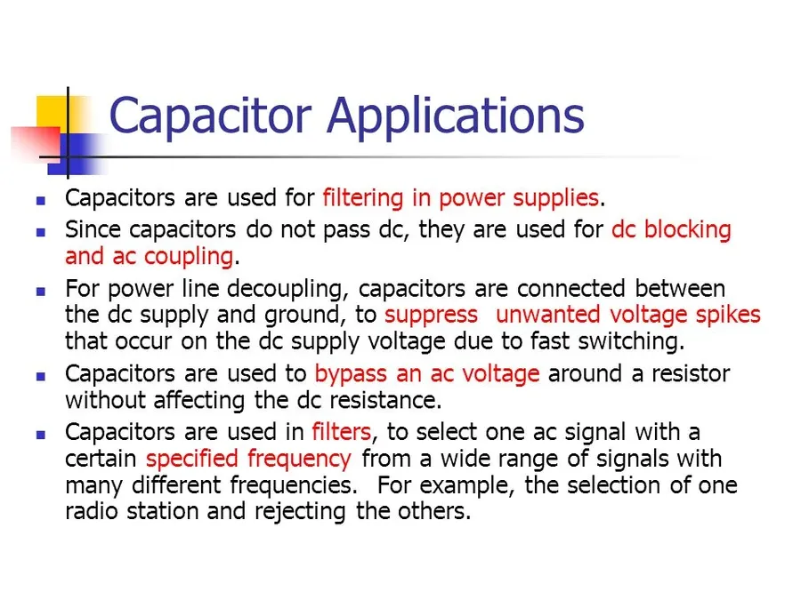
Capacitors, measured in microfarads (µF), are ubiquitous in modern electronics, playing a crucial role in various applications due to their ability to store electrical energy. Their diverse applications are a testament to their versatility and importance in circuit design, ranging from smoothing voltage fluctuations to enabling complex signal processing.
- Power Supplies
Capacitors with microfarad ratings are essential for filtering and smoothing DC output in power supplies. These capacitors help reduce ripple and provide a more stable voltage to electronic devices, ensuring proper operation. - Audio Equipment
In audio circuits, microfarad capacitors are used for filtering, coupling, and decoupling signals. They are key components in equalizers, amplifiers, and crossover networks, enabling clear and high-quality audio reproduction. - Motor Starting Circuits
Single-phase induction motors often rely on capacitors with specific microfarad values to provide the necessary starting torque. These capacitors help initiate the motor's rotation and allow it to run smoothly. - Smartphones and Mobile Devices
Capacitors are extensively used in smartphones and mobile devices for power management, signal processing, and touch sensing. Their compact size and high efficiency make them ideal for portable electronics. - LED Lighting
Capacitors play a vital role in LED lighting systems, helping to regulate current and reduce flicker. The correct microfarad values are crucial for the smooth and efficient operation of LED drivers. - Automotive Electronics
Modern cars use numerous capacitors for various functions, from engine control units to infotainment systems. Capacitors with appropriate microfarad values are used for filtering, energy storage, and signal conditioning in these critical systems. - Industrial Equipment
In industrial machinery and equipment, microfarad capacitors are used in motor drives, power supplies, and control systems to provide reliable performance and maintain efficiency. These applications often require high-voltage and high-temperature rated components.
The selection of the correct microfarad value is critical in all these applications. Using an incorrectly sized capacitor can lead to performance issues, component failure, or even damage to the equipment. Therefore, understanding the specific microfarad rating required for a given circuit is essential for proper design and maintenance.
Measuring Microfarads with Multimeters
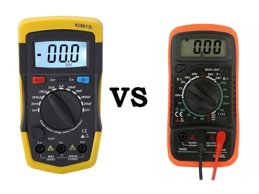
Multimeters are indispensable tools for accurately determining the capacitance, measured in microfarads (µF), of capacitors, both in standalone components and within electronic circuits. This section will provide a detailed, step-by-step guide on how to use a multimeter for microfarad measurements, along with best practices for capacitor testing.
- Safety First
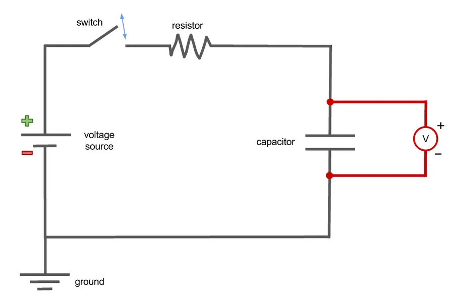
Before testing any capacitor, ensure that the circuit is powered off and that the capacitor is fully discharged to prevent electrical shock or damage to the multimeter. Use a suitable discharge tool or resistor to safely dissipate any stored charge. - Select Capacitance Mode
Turn on the multimeter and select the capacitance measurement mode, usually denoted by 'F' or a capacitor symbol (⟮). If your multimeter has multiple capacitance ranges, start with the highest range to avoid overloading the meter, and adjust to a lower range for a more precise reading if necessary. - Prepare the Capacitor
For in-circuit measurements, disconnect at least one terminal of the capacitor from the circuit to avoid parallel capacitance readings from other components. For isolated capacitors, ensure the terminals are clean and easily accessible. - Connect the Multimeter Leads
Connect the multimeter test leads to the capacitor terminals. Polarity matters for polarized capacitors (electrolytic and tantalum types), ensure the positive (+) lead of the multimeter connects to the positive terminal of the capacitor and the negative (-) lead connects to the negative terminal. For non-polarized capacitors, polarity does not matter. - Observe the Reading
Once the leads are connected, observe the multimeter's display. Allow a few seconds for the meter to stabilize and display a steady reading in microfarads (µF). Some multimeters may display a value close to zero initially, this is normal. - Interpret and Record Results
Record the displayed microfarad reading. Compare this value to the capacitor's marked or specified capacitance. If the measured value deviates significantly (typically more than 20%) from the specified value, the capacitor may be faulty and require replacement. Be aware of capacitor tolerance as well. - Repeat as Needed
If testing multiple capacitors or circuits, repeat these steps for each component. It is good practice to confirm measurements for precision.
It's essential to understand that multimeter measurements are subject to a certain degree of uncertainty. Environmental factors and the multimeter’s accuracy will influence the reading. Therefore, a reading within the tolerance specification of the capacitor is considered normal.
Testing capacitors with a multimeter allows for a preliminary assessment of their health. For more advanced testing, such as checking the capacitor's equivalent series resistance (ESR) or leakage current, specialized equipment is required.
Selecting the Correct Microfarad Value
The selection of a capacitor with the precise microfarad (µF) rating is a critical aspect of effective circuit design. An appropriate capacitance value ensures optimal circuit performance, while deviations can lead to malfunctions or inefficiencies. The microfarad rating directly dictates the capacitor's charge storage capacity, making it a key parameter in circuit functionality.
When specifying a capacitor for a circuit, it's crucial to match the designed capacitance as closely as possible. This is dictated by the circuit's operational requirements and characteristics such as time constants, filtering requirements, or energy storage needs. Using capacitors with incorrect microfarad values, whether higher or lower than specified, can have several adverse effects:
- Reduced Performance
Capacitors significantly lower than the specified value may not provide the necessary charge storage or timing characteristics. This leads to instability in circuits, inadequate filtering, or timing inaccuracies. - Circuit Malfunction
Incorrect capacitance can lead to oscillations or instability in signal frequencies. For instance, in timing circuits, an under or oversized capacitor will alter the duration of timing pulses, causing the circuit not to operate correctly. - Overheating and Damage
In certain applications, such as power supply smoothing, capacitors with insufficient capacitance may not effectively handle the current demands, leading to overheating and potential failure. Conversely, a capacitor with significantly higher capacitance can lead to larger inrush currents and stress other components of the circuit. - Increased Noise
In filtering circuits, an incorrect capacitor rating may not effectively eliminate high-frequency noise or ripple, leading to poor performance in analog and digital systems.
The tolerance of a capacitor's microfarad rating also plays a significant role. Capacitors are generally available with a certain tolerance range (e.g., ±5%, ±10%), this means that the actual measured capacitance value may vary from its stated value. It's crucial to select a component with a tolerance that is acceptable for the specific application. For highly sensitive circuits, capacitors with tighter tolerances (e.g., ±1%) may be required.
In summary, selecting the correct microfarad value is a fundamental step in circuit design. A meticulous selection process and an understanding of the required capacitance and tolerances are necessary to ensure optimal performance and longevity of the electronic devices.
Frequently Asked Questions About Microfarads
This section addresses common queries regarding microfarads (µF), a fundamental unit for measuring capacitance. Understanding these questions will enhance your comprehension of how microfarads function within electrical circuits and components.
- What are microfarads (µF) in a capacitor?
Microfarads (µF) quantify a capacitor's ability to store an electrical charge. One microfarad represents one millionth of a farad, and this smaller unit is commonly used because farads represent a very large amount of capacitance. The higher the microfarad rating, the greater the capacitor's capacity to hold charge at a given voltage. - How do you convert microfarads (µF) to farads (F)?
To convert microfarads to farads, divide the value in microfarads by 1,000,000. Mathematically, this is represented as: Farads (F) = Microfarads (µF) / 1,000,000. For example, 1,000,000 µF is equal to 1 F. - What does 50 µF mean on a capacitor?
A marking of 50 µF on a capacitor indicates that the capacitor has a capacitance of 50 microfarads. This means it can store a specific amount of electrical charge relative to its design and operating voltage and is 50 millionths of a farad. - What is 200 µF equal to in farads?
200 µF is equal to 0.0002 farads (F). This is calculated by dividing 200 by 1,000,000: 200 µF / 1,000,000 = 0.0002 F. This highlights the significantly smaller scale of microfarads relative to farads. - Why are microfarads used instead of farads in most practical applications?
Farads represent an extremely large unit of capacitance. Most electronic applications require much smaller capacitance values, hence the use of microfarads (µF). Using microfarads allows for more manageable numerical values when specifying and working with capacitor ratings in practical circuits. It's analogous to using millimeters instead of meters for small measurements. - Can a capacitor's microfarad value change over time?
Yes, a capacitor's microfarad value can change slightly over time due to aging, temperature variations, and operating conditions. This drift in capacitance can affect circuit performance, emphasizing the need to adhere to manufacturer specifications and consider tolerances in critical applications. Also, physical damage and internal dielectric breakdown can substantially change the capacitance. - How does the voltage rating of a capacitor relate to its microfarad (µF) rating?
The voltage rating of a capacitor is a separate specification from its microfarad value. The voltage rating indicates the maximum voltage that the capacitor can safely withstand without failure, while the microfarad value describes the capacitor's capacity to store charge. Both parameters are critical when selecting a capacitor for a specific application and must not be exceeded to avoid damage.
Microfarad Symbol and Terminology

The microfarad (µF) symbol is a crucial component of electrical engineering and electronics, representing a unit of capacitance equal to one millionth of a farad. Its precise usage and correct terminology are essential for accurate communication in technical contexts.
- Microfarad Symbol (µF)
The microfarad symbol is represented by the Greek letter 'mu' (µ) followed by a capital 'F'. This symbol (µF) is universally recognized and used in circuit diagrams, component specifications, and technical documentation. The 'µ' denotes the prefix 'micro', indicating a factor of 10⁻⁶. - Use on Diagrams
In schematic diagrams, the microfarad value is typically placed adjacent to the capacitor symbol. For example, a capacitor rated at 10 microfarads will be labeled as 10µF. The symbol clearly indicates the specific capacitance of that component. - Use in Specifications
In product datasheets and component specifications, the capacitance is often explicitly stated in microfarads (µF). This provides engineers and technicians with the necessary information to select the appropriate components for a particular application. Proper symbol and notation ensures there is no confusion with other units of capacitance. - Terminology
When discussing capacitance values, it's important to use the correct terminology. The term 'microfarad' should be used rather than simply 'micro' or just 'F'. For example, one should say 'a 10 microfarad capacitor' instead of 'a 10 micro capacitor' or 'a 10 F capacitor'. - Related Units and Prefixes
While microfarads are a common unit, it's helpful to understand related units and prefixes. The farad (F) is the base unit of capacitance, but it's very large. Smaller units such as the nanofarad (nF), which is equal to 10⁻⁹ farads, and picofarad (pF), which is equal to 10⁻¹² farads, are also commonly used. Understanding these prefixes enables you to accurately represent capacitance values in different ranges.
Microfarads (µF) are a cornerstone of electronics, representing a unit of capacitance that allows for the storage of electrical charge. From basic circuits to advanced tech, the understanding of microfarads, their application in capacitors and practical use is essential for anyone involved in electronics. As technology evolves, the importance of microfarads will remain vital for innovations in electronics and beyond. Whether in the design of next-gen microchips or managing the energy needs of our homes, a clear understanding of microfarads allows us to harness the power of electricity safely and efficiently, paving the way for technological advancement.