Understanding the 1000uF 35V Capacitor: Uses, Specs, and Selection
In the vast realm of electronics, components like the 1000uF 35V capacitor often go unnoticed, yet they're vital for the stable operation of numerous devices. Just as a keystone supports an arch, these capacitors ensure that electrical circuits function smoothly, filtering noise and storing energy. From smoothing out power fluctuations in drone flight controllers to providing stable power in computer motherboards, the 1000uF 35V capacitor is an essential workhorse. This article will delve deep into what makes this component crucial, its specifications, how to choose the right one, and address common questions, providing practical insights and guiding you through the proper selection and use of this ubiquitous part.
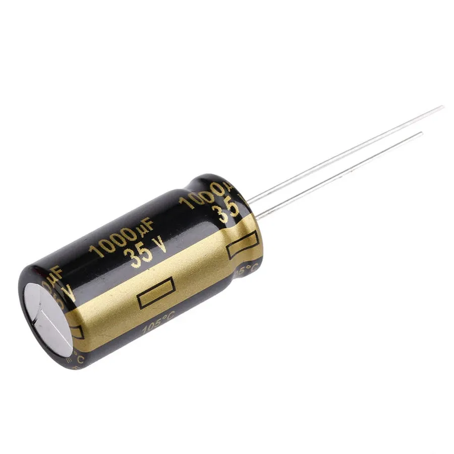
What is a 1000uF 35V Capacitor?
A 1000uF 35V capacitor is an electrolytic capacitor characterized by its capacitance of 1000 microfarads (µF) and a maximum voltage rating of 35 volts (V). These parameters are crucial for its function as a charge storage device in electronic circuits, enabling energy storage and filtering, playing a pivotal role in maintaining stable power delivery.
Key Specifications and Their Importance
Understanding the specifications of a 1000uF 35V capacitor is crucial for its proper application and performance within electronic circuits. These specifications dictate the capacitor's behavior and limitations, and selecting a component without considering them can lead to circuit malfunction or failure. Key parameters include capacitance, voltage rating, tolerance, temperature range, Equivalent Series Resistance (ESR), and physical dimensions.
| Specification | Value | Importance |
|---|---|---|
| Capacitance | 1000uF | Indicates the capacitor's ability to store electrical charge. Higher capacitance allows for greater charge storage and is crucial for filtering and energy storage applications. |
| Voltage Rating | 35V | Specifies the maximum voltage the capacitor can safely withstand. Operating beyond this limit can cause dielectric breakdown, leading to capacitor failure and potential circuit damage. |
| Tolerance | ±20% | Indicates the acceptable variation in the actual capacitance value from the nominal rating. A tighter tolerance provides more consistent performance but usually at a higher cost. |
| Temperature Range | Typically -40°C to +105°C | Defines the temperature range within which the capacitor can operate reliably. Exceeding this range can lead to parameter drift and accelerated aging, causing performance degradation. |
| ESR (Equivalent Series Resistance) | Varies (lower is better) | Represents the internal resistance of the capacitor. Lower ESR results in better efficiency for filtering and energy storage by minimizing heat dissipation and voltage drops. |
| Case Size | e.g., 10x20mm or 12.5x25mm | The physical dimensions are a crucial parameter in design to ensure the capacitor fits within the available space on the PCB. |
Common Applications of the 1000uF 35V Capacitor
The 1000uF 35V capacitor is a versatile component widely used across various electronic applications due to its ability to store and release electrical energy. Its primary function revolves around smoothing power delivery, filtering unwanted noise, and providing stable voltage levels, thereby protecting sensitive circuit components from damage caused by voltage fluctuations or spikes.
Specifically, the 1000uF 35V capacitor finds extensive use in the following areas:
- Power Filtering
In power supplies and voltage regulators, these capacitors act as filters, smoothing out the rectified AC voltage to provide a stable DC output. This reduces ripple and noise, crucial for reliable operation of downstream circuits. - Decoupling
Capacitors placed near integrated circuits (ICs) and other active components provide local energy reserves, quickly supplying current when the component’s demand increases and preventing voltage drops. This decoupling action helps maintain stable voltage levels crucial for proper digital and analog operation. - Energy Storage
While not designed for long-term energy storage like batteries, these capacitors can temporarily hold charge, allowing circuits to ride through brief power interruptions or voltage dips. They are used in applications where brief buffering is needed before more substantial power storage takes over or when a sudden surge of current is required. - Signal Smoothing
In circuits dealing with variable signals, these capacitors help smooth out the signal by filtering out high-frequency components and noise. This ensures that the intended signal waveform is delivered with minimum distortion. Typical in audio applications, as well as some control systems - Specific Device Applications
They are commonly found in flight controllers for drones, computer motherboards for power delivery to CPU and RAM, and other general electronic devices that require a regulated power supply. They are also essential in switch mode power supplies (SMPS), DC to DC converters, as well as various power stages in general electronics.
Selecting the Right 1000uF 35V Capacitor
Choosing the appropriate 1000uF 35V capacitor is crucial for ensuring the reliable operation of electronic circuits. This selection process involves careful consideration of various factors, including the operating voltage, temperature, equivalent series resistance (ESR), physical size constraints, and the desired lifespan of the component. Each of these parameters plays a vital role in the capacitor's performance and longevity.
| Parameter | Description | Impact on Selection |
|---|---|---|
| Operating Voltage | Maximum voltage the capacitor can withstand without failure. | Must be greater than the maximum voltage in the circuit; derating is recommended for reliability. |
| Temperature Range | The range of ambient temperatures within which the capacitor will function correctly. | Should match the expected operating environment. Exceeding temperature limits reduces lifespan. |
| Equivalent Series Resistance (ESR) | Internal resistance of the capacitor, contributing to heat generation and voltage drop during operation. | Lower ESR results in less power dissipation and better performance, especially in power filtering applications. |
| Physical Size | Physical dimensions of the capacitor, which can be critical in compact designs. | Must fit within the available space on the PCB; consider both diameter and height. |
| Lifespan | Expected operational life of the capacitor under specified conditions, often denoted in hours. | Select based on the device's overall lifespan requirements; higher lifespan capacitors are more reliable over the long term. |
To illustrate the practical implications of these parameters, let's compare two capacitor series from reputable manufacturers, Panasonic FC and Rubycon ZL, which are commonly used in various electronic applications.
| Feature | Panasonic FC Series | Rubycon ZL Series |
|---|---|---|
| ESR | Typically medium, suitable for general-purpose applications. | Lower than Panasonic FC, ideal for applications requiring high performance filtering or power supply smoothing. |
| Lifespan | Good lifespan, often in the range of 2000-5000 hours at 105°C. | Longer lifespan, can exceed 5000 hours at 105°C. |
| Temperature Range | -40°C to +105°C | -55°C to +105°C |
| Typical Use | Power supply filtering, general purpose decoupling. | Applications demanding high reliability and performance like high efficiency power conversion. |
Understanding Capacitor Polarity
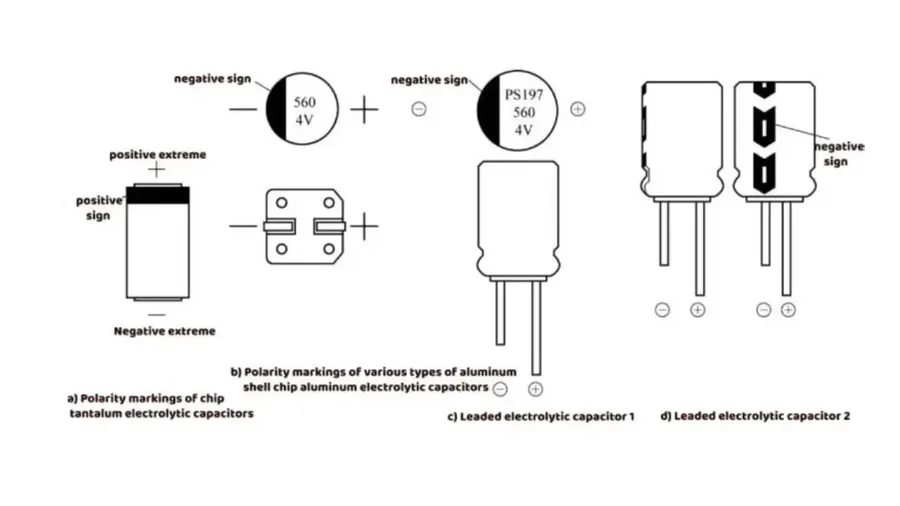
Electrolytic capacitors, such as the 1000uF 35V capacitor, are polarized components, meaning they have a designated positive and negative terminal. Correctly observing polarity is crucial for their proper function and preventing potential damage. Reversing the polarity can lead to overheating, gas build-up, bulging, and ultimately, capacitor failure.
- Identifying the Negative Lead
The negative lead of an electrolytic capacitor is typically marked with a stripe or a series of minus (-) signs printed on the capacitor's body, alongside the leads. It's also usually shorter in length compared to the positive lead. - Identifying the Positive Lead
The positive lead is usually unmarked on the capacitor, and it tends to be the longer lead. If unsure, always refer to the markings on the capacitor body or the manufacturer's datasheet. The circuit board should also have markings indicating polarity. - Consequences of Incorrect Polarity
Connecting an electrolytic capacitor in reverse polarity can cause a rapid build-up of internal pressure due to the electrochemical process, often resulting in component failure, or in extreme cases, an explosive rupture. This is dangerous and should always be avoided. - Visual Inspection
Before installation, carefully inspect the capacitor’s casing and lead markings to confirm correct polarity before soldering. Use a magnifying glass if the markings are difficult to see.
When to Consider Higher Voltage Capacitors
While it might seem counterintuitive, selecting a capacitor with a higher voltage rating than the circuit's operating voltage is often a prudent design practice. This is not about over-engineering; it's about ensuring long-term reliability and preventing catastrophic failure. Operating a capacitor consistently near its rated voltage accelerates degradation and increases the risk of breakdown, whereas using a higher voltage rating provides a safety margin.
The primary reason to use a capacitor with a higher voltage rating is to accommodate transient voltage spikes or fluctuations. Real-world circuits are rarely perfectly stable; they often experience short-term overvoltage conditions due to switching noise, inductive kickback, or power supply irregularities. If the applied voltage exceeds the capacitor's maximum rated voltage, the dielectric material can break down, leading to short circuits, permanent damage, and, in extreme cases, explosion and fire. Therefore, a higher voltage rating is essential for mitigating these risks. As a general rule of thumb, it's a common engineering practice to select a capacitor with a voltage rating at least 20% higher than the maximum expected voltage in the circuit. This rule helps in ensuring the capacitor operates well within its safety limits, which enhances device reliability and lifespan.
Frequently Asked Questions About 1000uF 35V Capacitors
This section addresses common inquiries regarding 1000uF 35V capacitors, providing clear and concise answers to help you better understand their function, usage, and selection.
- What is a 1000uF 35V capacitor typically used for?
A 1000uF 35V capacitor is commonly used for power filtering, decoupling, and energy storage in electronic circuits. Its high capacitance makes it suitable for smoothing power delivery, reducing noise, and maintaining stable voltage levels. It can be found in a wide range of applications such as computer motherboards, power supplies, and audio circuits. - What does the '1000uF' rating of a capacitor mean?
The '1000uF' rating specifies the capacitance of the capacitor, which is 1000 microfarads. Capacitance is a measure of the capacitor's ability to store an electrical charge. A higher capacitance means the capacitor can store more charge. The farad (F) is the base unit, but microfarads (µF) are more commonly used due to the typical values found in electronic circuits. - Can I use a 25V capacitor instead of a 35V capacitor?
No, it is generally not recommended to use a 25V capacitor in place of a 35V capacitor in a circuit designed for 35V. Using a lower voltage rating capacitor can lead to premature failure, potentially causing damage to the circuit due to the capacitor exceeding its voltage limit. The voltage rating should always meet or exceed the maximum expected voltage in the application. - What are the implications of using a 1000uF 50V capacitor instead of a 1000uF 35V capacitor?
Using a 1000uF 50V capacitor in place of a 1000uF 35V capacitor is generally acceptable. The 50V capacitor offers a higher voltage tolerance. It will function correctly in the circuit, provided all other specifications (like capacitance, ESR, and temperature rating) are met and the physical size is compatible. While this might come at a higher price point, using the 50V capacitor is often safer. It is better practice to exceed voltage rating than not meet it. - What are the differences between radial and axial leaded capacitors?
Radial and axial refer to the lead orientation. Radial capacitors have both leads exiting from the same side of the capacitor body, which is common for through-hole mounting on printed circuit boards. Axial capacitors have leads extending from opposite ends of the capacitor, and are often mounted end to end on a board or in a point-to-point construction. The choice depends on space constraints and mounting requirements of the application. Functionally, there is no inherent difference in capacitance or voltage rating. - What does tolerance mean with respect to a capacitor?
Capacitor tolerance specifies the acceptable range of variation in its actual capacitance from the stated value. For example, a capacitor with a stated capacitance of 1000uF and a tolerance of ±20% could have a capacitance between 800uF and 1200uF. Understanding tolerance is important to ensure that circuits function as intended. While variations in this range would still function, critical applications should have lower tolerances. - How important is the Equivalent Series Resistance (ESR) of a 1000uF 35V capacitor?
ESR is an important parameter that represents the inherent resistance within a capacitor. A high ESR can cause energy loss as heat, reducing efficiency, and can lead to performance issues in circuits, like unwanted ripple in power supplies. When selecting a capacitor, particularly in power-related circuits, ensure it meets the application's ESR requirements. Lower ESR values are generally desirable.
Troubleshooting Common Issues with 1000uF 35V Capacitors
Capacitor failure, while not always catastrophic, can lead to erratic circuit behavior or complete system malfunction. Recognizing the common symptoms of a failing 1000uF 35V capacitor is crucial for effective troubleshooting and timely replacement, thus preventing further damage to sensitive electronic components.
- Bulging or Swelling
A physically deformed capacitor, typically with a rounded or expanded top or side, indicates internal pressure build-up due to electrolyte degradation or excessive current. This is a clear sign of failure and requires immediate replacement. The 1000uF 35V electrolytic capacitor is prone to this symptom due to its construction. - Electrolyte Leakage
The presence of a corrosive, often sticky, substance around the base of the capacitor is a sign of electrolyte leakage. This is caused by seal failure due to overheating or age. Leaked electrolyte can cause corrosion on nearby components or PCB traces, which can cause secondary failures. - Decreased Capacitance
A drop in the actual capacitance value below the rated 1000uF, often detectable using an LCR meter. This happens over time due to drying of the electrolyte, which is a common failure mode, especially in higher temperature applications. Even if there are no visible signs of damage, decreased capacitance will impair the capacitor's ability to perform its circuit function. - Increased ESR (Equivalent Series Resistance)
An increase in ESR, not always readily measurable without a specialized ESR meter, will lead to higher heat dissipation in the capacitor, reduced ripple current capability and thus, a loss of its ability to properly filter. A high ESR might not be apparent but will negatively impact circuit performance and may lead to other failures. - Open Circuit or Short Circuit
While less frequent than the above, a capacitor can fail completely and result in an open circuit condition (no connection) or, more dangerously, a short circuit. An open capacitor will fail to perform the intended circuit function and short circuit failure will lead to major damage to the device under power. - Intermittent Issues or Malfunctions
A failing capacitor may not always manifest obvious symptoms, and instead show up as intermittent glitches, instability, or erratic behavior in the circuit. The capacitor may only show symptoms when under load or when temperature increases due to operation. If a system shows unexplainable issues that cannot be traced to other sources, suspect a failing capacitor.
The 1000uF 35V capacitor, although a small component, plays a vital role in countless electronic applications. This article provided a detailed look at its specifications, uses, and selection process. Remember that selecting the right capacitor, like a 1000uf 35v capacitor, is essential for the stable and efficient operation of any electronic device. By understanding the intricacies of these small but powerful components, we can build better circuits and extend the life of our electronics. The evolution of capacitor technology continues, promising even more efficient and compact components in the future. We encourage further exploration and experimentation within the electronics community and hope this has been an enlightening journey.