Understanding the 104 Capacitor: Specs, Uses, and Replacements
In the realm of electronics, the 104 capacitor is a workhorse, silently managing electrical flow in countless devices, from your smartphone to your computer. Marked with '104,' this small component, also known as a 0.1uF capacitor, plays a critical role in ensuring stable and efficient operation. Understanding its specifications and applications is essential for anyone working with electronics or even just curious about the gadgets we use daily. This article will demystify the 104 capacitor, exploring its core characteristics, practical uses, and how to deal with it in various scenarios.
Decoding the 104: What Does the Marking Mean?
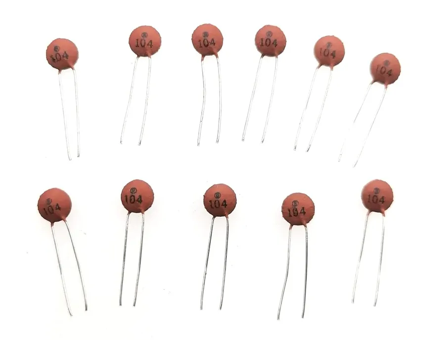
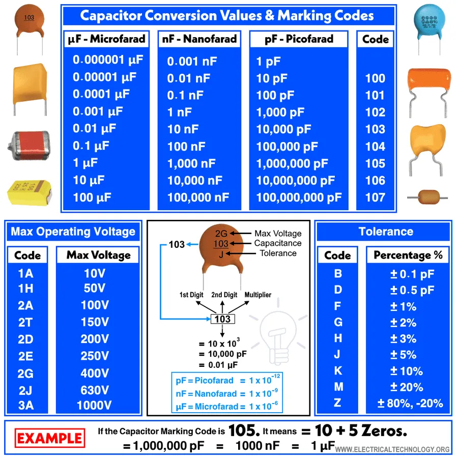
The marking '104' on a capacitor is a standardized code that indicates its capacitance value, a crucial parameter determining its ability to store electrical charge. This code isn't arbitrary; it provides a concise method for identifying the capacitor's rating. Specifically, a '104' marking denotes a capacitance of 100,000 picofarads (pF), which is equivalent to 0.1 microfarads (µF). This value is fundamental to understanding how the capacitor will behave within an electronic circuit, influencing its application in filtering, decoupling, and energy storage.
| Digit Code | Value (pF) | Value (µF) |
|---|---|---|
| 104 | 100,000 | 0.1 |
104 Capacitor Value in Different Units: pF, nF, and uF
The '104' code on a capacitor denotes its capacitance value, which is essential for circuit design and analysis. While the code itself represents a value in picofarads (pF), understanding its equivalent in nanofarads (nF) and microfarads (µF) is crucial for practical applications. This section clarifies these conversions, ensuring a consistent comprehension of the 104 capacitor's capacity.
| Unit | Value | Relationship |
|---|---|---|
| Picofarads (pF) | 100,000 pF | Base value derived directly from the '104' code. |
| Nanofarads (nF) | 100 nF | 1 nF = 1,000 pF; therefore, 100,000 pF / 1000 = 100 nF. |
| Microfarads (µF) | 0.1 µF | 1 µF = 1,000,000 pF; therefore, 100,000 pF / 1,000,000 = 0.1 µF. |
The 104 Capacitor's Role in Electronic Circuits
The 104 capacitor, characterized by its 0.1µF capacitance, is a ubiquitous component in electronic circuits, performing essential functions such as decoupling, filtering, and energy storage. These roles are critical to ensure the stable and efficient operation of electronic devices.
- Decoupling
104 capacitors are frequently used for decoupling, also known as bypass. In this role, they are placed near integrated circuits (ICs) to shunt high-frequency noise and transients to the ground. This ensures a stable voltage supply for the IC, preventing erratic behavior and signal corruption. - Filtering
As filter components, 104 capacitors are utilized in conjunction with resistors or inductors to selectively pass or block specific frequencies in a circuit. They can be found in low-pass, high-pass, band-pass, and notch filters. For instance, a 104 capacitor can help reduce noise in an audio signal or filter out unwanted electromagnetic interference (EMI). - Energy Storage
Although 104 capacitors have a relatively small capacitance value, they can still store a limited amount of electrical energy. This feature enables them to quickly provide small bursts of power for circuit operations or act as a buffer for sudden changes in voltage or current, playing a role in smoothing circuit behavior.
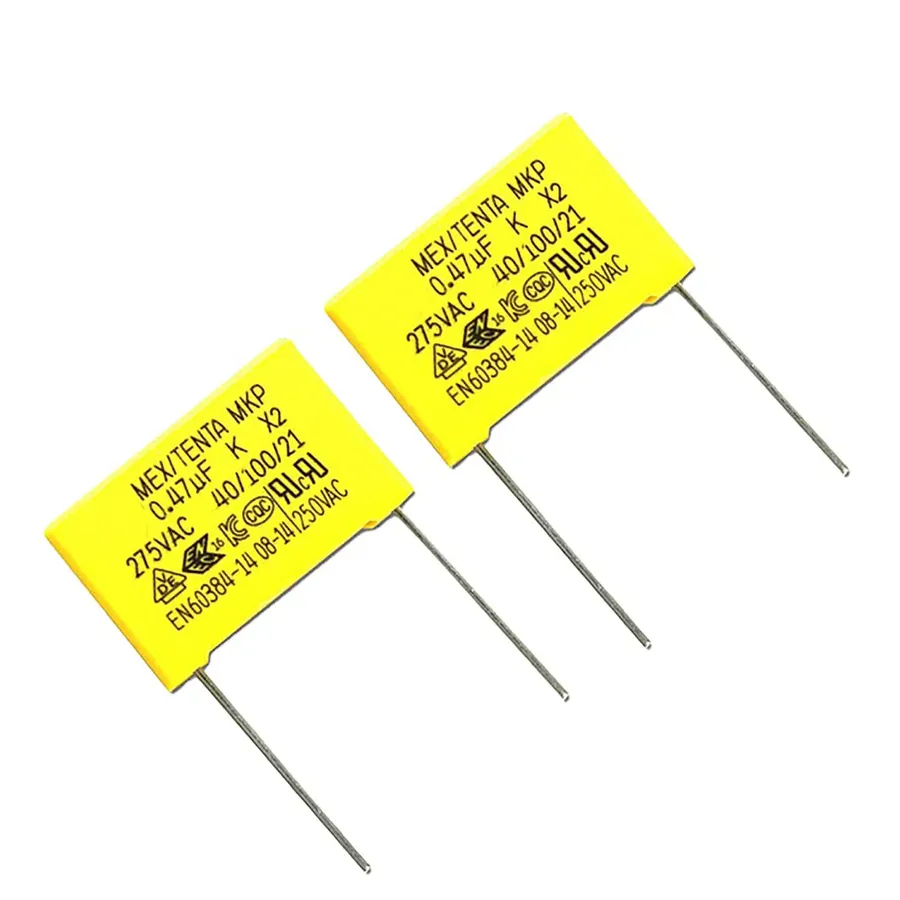
Types of 104 Capacitors: Ceramic, Film, and More

While the '104' marking denotes a specific capacitance value, capacitors themselves come in diverse types, each with unique characteristics that make them suitable for different applications. Understanding these types—primarily ceramic and film—is crucial for effective circuit design and repair. This section will help differentiate between them.
| Feature | Ceramic Capacitors (MLCC) | Film Capacitors |
|---|---|---|
| Construction | Multiple layers of ceramic and metal electrodes | Thin plastic film dielectric with metal electrodes |
| Capacitance Range | Typically low to medium (picofarads to a few microfarads) | Medium to high (nanofarads to several microfarads) |
| Voltage Rating | Wide range, including low and high voltage versions | Moderate to high voltage handling |
| Tolerance | Typically wider tolerances | Generally better tolerances than ceramic |
| Temperature Stability | Can exhibit capacitance change with temperature (temperature coefficient) | More stable capacitance over temperature |
| Polarity | Non-polarized | Non-polarized |
| Size | Compact and small form factor | Larger physical size for comparable capacitance and voltage |
| Cost | Relatively inexpensive | Typically more expensive |
| Typical Applications | Decoupling, filtering, bypass applications in general electronics | Precision timing circuits, audio equipment, power supplies |
Beyond ceramic and film types, other less common 104 capacitor types exist, each offering specific advantages. Tantalum capacitors, while less common for the 104 code, provide high capacitance in a small form factor and are often used for power filtering applications where stability is key. Electrolytic capacitors are also available for higher capacitances and are polarized, making them unsuitable for certain circuit areas. However, these are rarely found with a '104' marking due to their high-capacitance characteristics, which means they usually require a different three digit code for their value.
Selecting the correct type of 104 capacitor is paramount for performance. Ceramic capacitors, particularly MLCCs, dominate general-purpose applications due to their low cost and compact size. Film capacitors are preferred for applications requiring greater stability, lower losses, and precision. The choice is further influenced by the project's temperature conditions and cost targets. Consider the pros and cons of each type of 104 capacitor before making your decision. By carefully matching the characteristics of each capacitor to the circuit's demands, engineers can ensure optimal functionality and reliability.
104 Capacitor Voltage Ratings: What You Need to Know
While the '104' marking specifies a capacitor's capacitance, the voltage rating is an equally critical parameter that dictates the maximum voltage a capacitor can withstand without failing. Understanding and adhering to a 104 capacitor's voltage rating is crucial for ensuring circuit reliability and preventing potential damage.
A capacitor's voltage rating, usually specified in volts (V), signifies the peak voltage that can be safely applied across the capacitor's terminals. Exceeding this voltage can lead to dielectric breakdown, which results in capacitor failure. This breakdown can manifest as a short circuit, leading to component damage and potential board failures.
| Characteristic | Description |
|---|---|
| Voltage Rating | Maximum DC or AC voltage a capacitor can safely handle. |
| Impact of Exceeding Voltage Rating | Dielectric breakdown, capacitor failure, short circuit, potential component and board damage. |
| Selection Criterion | Choose a voltage rating greater than the maximum expected voltage in the application. A common safety factor is at least 20% over the maximum circuit voltage. |
| Standard Voltage Ratings | Common ratings include 16V, 25V, 50V, 100V, and higher. Consult datasheets for specific values. |
It is imperative to select a 104 capacitor with a voltage rating that comfortably exceeds the maximum voltage expected in the circuit. As a best practice, aim for a capacitor with a voltage rating at least 20% greater than the maximum circuit voltage to provide an adequate safety margin. Standard voltage ratings for 104 capacitors vary, including common values like 16V, 25V, 50V, 100V, and even higher, depending on the capacitor's type and intended application. Consult the capacitor's datasheet to determine the precise voltage rating. Using the wrong voltage rating can result in unreliable operation and premature capacitor failure.
Identifying a Bad or Failing 104 Capacitor
Like any electronic component, a 104 capacitor can degrade or fail over time, impacting circuit performance. Identifying these failures early can prevent more significant issues. This section outlines key methods for recognizing a faulty 104 capacitor, encompassing both visual inspection and electrical testing techniques.
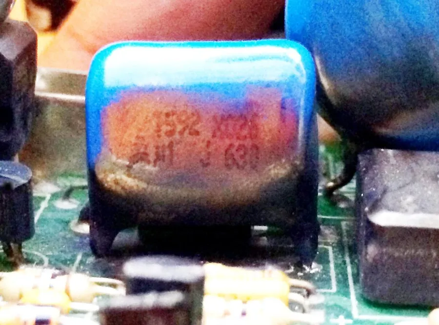
- Visual Inspection
Begin with a careful visual check for physical deformities. Look for signs such as bulging, cracking, or discoloration of the capacitor body. Leaking electrolyte, often seen as a sticky residue, is another clear indicator of failure, particularly in electrolytic types. Damaged or detached leads also signify a problematic capacitor. - Capacitance Measurement
Use a multimeter with a capacitance measurement function to verify the capacitor's value. A healthy 104 capacitor should measure approximately 0.1 uF (or 100nF or 100,000pF). A significant deviation from this value indicates a degradation in its capacity. Readings that are substantially lower or indicate an open circuit confirm failure. - ESR (Equivalent Series Resistance) Measurement
The ESR is a critical parameter that increases as a capacitor degrades. Use an ESR meter to measure the capacitor's resistance. Elevated ESR values, significantly above the manufacturer's specification (if available) or compared to a known good capacitor, suggest a failing component. This is especially relevant for electrolytic capacitors, where ESR changes dramatically with age. - Short Circuit Testing
A shorted capacitor presents as a very low resistance reading on a multimeter set to measure resistance. This indicates an internal breakdown of the dielectric, causing the capacitor to behave as a conductor rather than a charge storage device. Note that this test should be done with the capacitor removed from the circuit. - Effects of Capacitor Failure on Circuit Behavior
A failing 104 capacitor can cause various symptoms in a circuit, including signal distortion or noise, intermittent operation, complete circuit failure, or erratic behavior. In power supply circuits, it might result in inadequate smoothing, leading to instability. It's important to recognize these symptoms as they can point towards a faulty capacitor before a total breakdown.
Replacing a 104 Capacitor: A Practical Guide
Replacing a 104 capacitor, while generally straightforward, requires careful execution to ensure circuit integrity and safety. This section details a step-by-step guide to replacing these common components on printed circuit boards (PCBs).
- Gather necessary tools and materials
You will need a soldering iron with a fine tip, solder wire (preferably rosin core), desoldering braid or a solder sucker, tweezers, wire cutters, and a replacement 104 capacitor with the correct specifications (including capacitance, voltage rating, and tolerance). A multimeter is also beneficial for testing before and after replacement. Ensure you have a well-lit and ventilated workspace. - Prepare the work area and circuit board
Turn off and unplug the device you will be working on. If possible, discharge any remaining energy from the circuit by using a suitable discharge tool on the capacitor leads. Ensure the PCB is stable and secure on your work surface to prevent movement during the repair process. Ground yourself to avoid electrostatic discharge, which can damage sensitive electronic components. Wearing anti-static wrist strap is highly recommended. - Locate the faulty 104 capacitor
Carefully examine the PCB to find the faulty 104 capacitor which may be discolored, bulged, or leaking. Refer to the circuit schematics if available. Make a note of the capacitor's orientation to ensure correct installation of the new component, especially if it's polarized (though 104 capacitors are typically not polarized). - Desolder the faulty capacitor
Heat the solder joints of the capacitor leads with the soldering iron. Once the solder is molten, use the desoldering braid or solder sucker to remove the solder. Alternate between applying heat and using desoldering tools to remove all solder from the leads. Avoid excessive heat as this can damage the circuit board or components. Carefully detach the faulty capacitor. - Prepare the replacement capacitor
If the replacement capacitor leads are too long, trim them to match the original capacitor's lead length. Be certain to double-check that the replacement capacitor matches the old capacitor with regards to capacitance and other key specs, such as voltage rating. Failure to replace a capacitor with the correct specification can cause a failure of the device and damage to other parts. - Install the new capacitor
Place the new capacitor into the designated position on the PCB, ensuring that it is oriented the same way as the original component. If necessary, gently bend the leads of the component, so the body of the capacitor sits flush with the circuit board. Solder each lead to the PCB pads, ensuring a strong electrical connection. Apply solder sparingly and only heat the solder pads and component leads long enough to achieve a solid connection, to avoid damage from overheating. - Clean the work area
After soldering, clean any residual flux from the PCB using a specialized circuit board cleaner and a soft brush or q-tip. Remove any leftover solder or lead clippings. - Test the circuit
Before reassembling the device, use a multimeter to test the circuit and confirm the correct installation of the new capacitor. Measure resistance, and verify the replaced capacitor functions as expected. Then, reassemble the device and test. If the device still has issues, further debugging may be required.
Frequently Asked Questions about 104 Capacitors
This section addresses common questions about 104 capacitors, providing clear and concise answers to help clarify any remaining doubts and offer further practical information. We'll explore the nuances of their behavior and application in electronic circuits, drawing from fundamental principles and authoritative data to ensure accuracy and depth.
- What is the capacitance value of a 104 capacitor?
A 104 capacitor has a capacitance of 100,000 picofarads (pF), which is equivalent to 100 nanofarads (nF) or 0.1 microfarads (μF). The '104' designation is a standard EIA code, where the first two digits represent the significant figures and the third digit represents the multiplier. Thus, '10' followed by '4' zeros gives 100,000 pF. This value is critical for understanding the capacitor's behavior in a circuit. - What is the difference between a 103 capacitor and a 104 capacitor?
The primary difference lies in their capacitance values. A 103 capacitor has a value of 10,000 pF (10 nF or 0.01 μF), while a 104 capacitor is 100,000 pF (100 nF or 0.1 μF). This tenfold difference significantly impacts their application in circuits. The 103 capacitor is used where a smaller capacitance is needed, and a 104 where a larger one is necessary. - What constitutes a 'bad' reading for a capacitor, and how can I identify a faulty 104 capacitor?
A bad capacitor reading typically indicates a significant deviation from the expected capacitance value, such as open-circuit or short-circuit conditions, excessive Equivalent Series Resistance (ESR), or a reduced capacitance due to dielectric degradation. Using a capacitance meter, if the measured value is significantly different from 0.1uF, it is considered bad. Visual inspection for bulging, leakage, or discoloration may also indicate capacitor failure. A faulty capacitor will also cause circuit malfunctions, this is often the easiest way to identify if a capacitor has gone bad. - What are the typical applications of a 10 microfarad capacitor compared to a 104 capacitor?
A 10 microfarad (µF) capacitor has a significantly larger capacitance than a 104 capacitor (0.1 µF). While the 104 is suitable for high-frequency decoupling, signal filtering, and timing circuits, the 10 µF capacitor is often used in applications requiring more energy storage or low-frequency filtering, such as power supply smoothing, audio coupling, and large ripple current handling. Their selection is dictated by the circuit's specific needs. - Can a 104 capacitor be used in place of a 103 capacitor?
While technically possible, substituting a 104 capacitor for a 103 may cause circuit malfunction if precise capacitance values are needed in that section of the circuit. Since the 104 has ten times more capacitance than a 103, you may alter the time constant of an RC circuit, for example, or cause a circuit to function improperly. Unless precise calculations confirm it will not cause any issues, it's not recommended unless absolutely necessary. - What should I consider when choosing a replacement 104 capacitor?
When replacing a 104 capacitor, ensure that the replacement matches both the capacitance value (0.1 uF) and the voltage rating. Additionally, consider the capacitor type (ceramic, film, etc.), its tolerance, temperature coefficient, and physical size to ensure it fits the designated space on the PCB and meets operational requirements. Always select a replacement with equal or better specifications than the original.
The 104 capacitor, despite its small size, is a crucial element in electronics. Understanding its value (0.1uF), voltage rating, and applications is important for anyone involved in circuit design, repair, or even basic electronics understanding. From decoupling to filtering, the 104 capacitor plays an important role in shaping the functionality and stability of our digital world. By grasping these core concepts, we can better appreciate the complexities of modern technology and gain confidence in working with electronics.