Understanding the 15 Ohm Resistor: Applications & Selection
In the realm of electronics, the 15 ohm resistor plays a crucial role in controlling current and voltage within circuits. Much like the water valve in our home regulates water flow, this tiny component regulates the flow of electrical current. This article dives into the world of 15 ohm resistors, exploring their purpose, various types, how to choose them, and even what the color codes mean. Let's unpack the function of this unsung hero of electronics.
What is a 15 Ohm Resistor?
A 15 ohm resistor is a fundamental electronic component designed to impede the flow of electrical current, presenting a specific resistance of 15 ohms. This controlled opposition to current flow is crucial in circuit design for limiting current, dividing voltage, and enabling various signal manipulation functions. Unlike other components which might amplify or switch current, a resistor, especially one with a precise value such as 15 ohms, serves as a predictable and consistent element within an electrical circuit.
The specific value of 15 ohms places it within a range of common resistance values used in a wide array of applications. It is different from very low ohm resistors used for current sensing or very high ohm resistors for high impedance circuits. A 15 ohm resistor might be selected when a moderate current limitation is needed, which would be too much for a high resistance and too little for low resistance. The selection of a 15 ohm resistor is often dictated by the specific circuit requirements, typically based on Ohm's Law, to manage both voltage and current flow.
Types of 15 Ohm Resistors and Their Characteristics
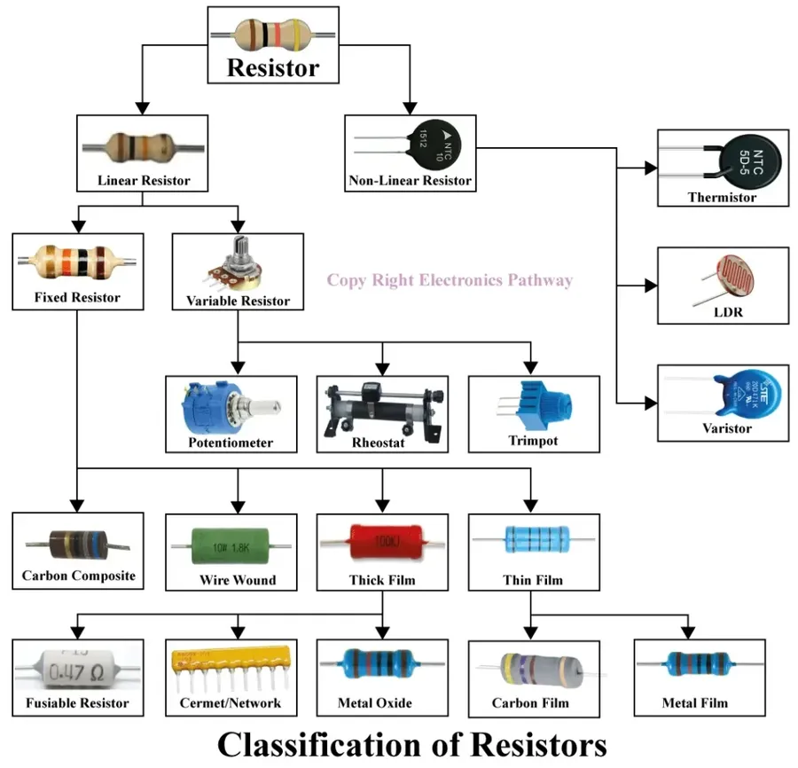
15 Ohm resistors, while sharing a common resistance value, come in various types, each tailored for specific applications and performance requirements. The choice of resistor type impacts factors such as precision, power handling, noise characteristics, and physical size, crucial considerations for any electronic design.
| Resistor Type | Description | Advantages | Disadvantages | Typical Applications |
|---|---|---|---|---|
| Metal Film Resistors | Precision resistors with a thin metal film deposited on a ceramic substrate. | High precision, low noise, good temperature stability. | More expensive than carbon film resistors. | Precision circuits, audio equipment, medical devices. |
| Carbon Film Resistors | General-purpose resistors with a carbon film deposited on a ceramic substrate. | Cost-effective, widely available. | Lower precision, higher noise, less temperature stability. | General electronics, hobbyist projects, less critical applications. |
| Wirewound Resistors | Resistors made by winding a wire around a ceramic core. | High power handling capability, robust. | Larger size, lower precision, inductive. | Power supplies, motor control, high-current applications. |
| Surface Mount Resistors (SMD) | Small, compact resistors designed for surface mounting on printed circuit boards. | Compact size, ideal for automated assembly, wide range of values. | Small size can make manual soldering difficult. | Modern electronics, consumer devices, compact PCB designs. |
Decoding the 15 Ohm Resistor Color Code
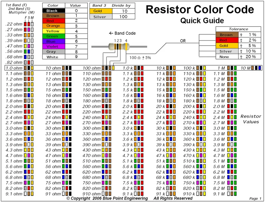
The color code on a 15 ohm resistor provides a standardized method for identifying its resistance value and tolerance. The bands are read sequentially from left to right, each representing a specific numerical value. Understanding this code is crucial for accurate identification of the resistor's properties without needing to use a multimeter.
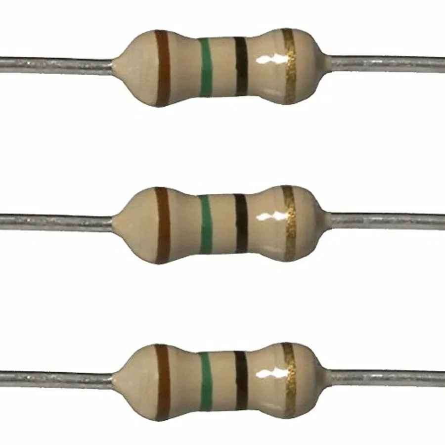
For a 15 ohm resistor, the most common color band sequence is as follows, assuming a 1% tolerance:
- Band 1 (First Digit)
Brown (represents 1) - Band 2 (Second Digit)
Green (represents 5) - Band 3 (Multiplier)
Black (represents a multiplier of 10^0 or 1) - Band 4 (Tolerance)
Brown (represents 1% tolerance)
Therefore, a resistor with a color sequence of Brown, Green, Black, Brown indicates a resistance of 15 ohms with a 1% tolerance. It is important to note that the tolerance band will vary based on the precision of the resistor.
| Tolerance Color | Tolerance Value |
|---|---|
| Brown | 1% |
| Red | 2% |
| Gold | 5% |
| Silver | 10% |
Applications of 15 Ohm Resistors
The 15 ohm resistor is a versatile component found in numerous electronic applications due to its ability to limit current, provide a specific load, or condition signals. Its resistance value makes it ideal for several common scenarios, ranging from protecting sensitive components to ensuring proper circuit functionality.
- Current Limiting in LED Circuits
A primary use of 15 ohm resistors is to limit the current flowing through LEDs. LEDs have specific current requirements, exceeding which can damage them. By placing a 15 ohm resistor in series with an LED, the current is regulated to a safe level, preventing burnout and ensuring optimal performance. This is particularly crucial when using LEDs with power sources that could provide excessive current. - Pull-Up or Pull-Down Resistors in Digital Logic
In digital circuits, 15 ohm resistors act as pull-up or pull-down resistors. These resistors ensure that a digital input is in a defined state when no active signal is present. A pull-up resistor connects an input to a high logic level (VCC), while a pull-down resistor connects it to a low logic level (ground). A 15 ohm resistor can be utilized for these tasks in certain digital logic families with lower input impedance requirements, or when a stronger pull is needed. - Signal Conditioning in Audio Circuits
In audio circuits, 15 ohm resistors play a role in impedance matching and signal conditioning. By carefully selecting the resistance value, these resistors help to properly load an audio signal source, ensuring efficient signal transfer and minimizing signal reflections. This can improve signal quality and reduce distortion in various audio applications. The 15 ohm value may be suitable in some specific impedance matching situations. - Load Resistors in Power Circuits
15 ohm resistors can also act as load resistors in power circuits. They are used to dissipate power in a predictable way, and this can be useful in testing circuits, simulating loads, or preventing overvoltage conditions. For instance, in power supply designs, a load resistor can ensure proper operation and stability when no load is present. However, this application requires consideration of the power rating of the resistor to avoid overheating.
Selecting the Right 15 Ohm Resistor: Power Rating and Tolerance
Selecting the appropriate 15 ohm resistor for a project hinges on understanding its power rating and tolerance. The power rating, measured in watts, dictates how much power the resistor can safely dissipate without overheating, while tolerance indicates the precision of the resistor's actual resistance value relative to its nominal 15 ohm rating. Proper selection ensures stable circuit operation and prevents component failure.
| Parameter | Description | Importance |
|---|---|---|
| Power Rating (Watts) | Maximum power a resistor can dissipate as heat without damage. | Critical to prevent overheating and ensure reliable operation. Select a resistor with a power rating at least twice the expected power dissipation in the circuit to provide a safety margin. |
| Tolerance (%) | Permissible deviation of actual resistance from nominal value. | Impacts circuit accuracy. Lower tolerance resistors are more precise and necessary for critical applications. Common tolerance values are 1%, 5%, and 10%. 5% is acceptable for most applications and 1% is needed for more precise measurements, timing, and filtering circuits. |
The resistor power rating should always be selected based on the power dissipation expected in the circuit using Joule's law, which is P=I²R or P=V²/R. The calculated power should be significantly less than the chosen resistor's rating. Consider an example where a 15 ohm resistor in a circuit has 0.2 Amps flowing through it, the power dissipation would be 0.6 Watts. In such cases it would be prudent to select a resistor with a rating of at least 1 Watt, and preferably 2 Watts for a safety margin. For tolerance, resistors with 5% tolerance are acceptable for most general-purpose applications but where precision is crucial, 1% tolerance or better should be selected.
15 Ohm Resistors and Ohm's Law: Calculation & Practical Usage
The 15 ohm resistor's behavior in electrical circuits is fundamentally governed by Ohm's Law, which states that the voltage (V) across a resistor is directly proportional to the current (I) flowing through it, with the resistance (R) being the constant of proportionality (V = IR). This section explores this relationship and provides practical applications on its use within circuits.
Understanding how to apply Ohm’s Law with a 15 ohm resistor is essential for circuit design and analysis. By manipulating the formula (I = V/R and R = V/I), we can calculate any one of these parameters if the other two are known. Here's how to apply these calculations in real-world scenarios:
- Calculating Current with a 15 Ohm Resistor
If a 5V source is applied across a 15 ohm resistor, the current flow can be determined by dividing the voltage by the resistance: I = 5V / 15Ω = 0.333A or 333 mA. This is a common scenario for LED current limiting applications. - Calculating Voltage Drop with a 15 Ohm Resistor
If a 0.2A current passes through a 15 ohm resistor, the voltage drop across the resistor will be: V = 0.2A * 15Ω = 3V. This is important in understanding how much voltage is being used by the resistor in the circuit and the voltage available for other components. - Calculating Resistance with Known Voltage and Current
If you know that a circuit has a 3V drop with a 0.2A current flowing through it, the resistance is R = 3V / 0.2A = 15Ω. This use case is typically encountered during circuit troubleshooting and component identification.
| Parameter | Formula | Example (15Ω Resistor) |
|---|---|---|
| Current (I) | I = V / R | With 5V: I = 5V / 15Ω = 0.333A |
| Voltage (V) | V = I * R | With 0.2A: V = 0.2A * 15Ω = 3V |
| Resistance (R) | R = V / I | With 3V & 0.2A: R = 3V / 0.2A = 15Ω |
Troubleshooting Issues with 15 Ohm Resistors
Effective troubleshooting of 15 ohm resistors involves identifying common failure modes such as overheating, physical damage, and incorrect resistance readings. Understanding these failure points is crucial for maintaining circuit integrity and ensuring reliable operation. This section will equip you with the knowledge to diagnose and rectify common issues, providing practical methods for testing resistors and identifying circuit problems stemming from resistor malfunctions.
- Overheating
Overheating typically occurs when the power dissipation exceeds the resistor's rated wattage, often resulting in visible discoloration or component failure. This commonly happens when the resistor is undersized for the application, leading to excessive heat generation. Check for higher than expected current flow in the circuit as this is most likely the root cause. - Physical Damage
Physical damage includes cracks, breaks, or burnt areas on the resistor body. This can be due to mechanical stress, impact, or excessive heat. A damaged resistor can lead to intermittent connections or a complete open circuit. Careful inspection under magnification is recommended. - Incorrect Resistance Readings
Inconsistent resistance readings measured by a multimeter can indicate a resistor that has drifted from its designed value. This might be due to manufacturing defects, degradation over time, or operation outside the specified temperature range. Use a calibrated multimeter to ensure accurate readings. - Open Circuit
An open circuit, indicated by infinite resistance, can happen due to severe overheating, physical breakage, or degradation. When a resistor fails open it ceases to perform any circuit function. Use a multimeter to test for continuity and locate such a failure. - Short Circuit
While less common, a resistor can fail as a short circuit by having a resistance of near zero. This usually results in excessive current flow and can damage other circuit components. Confirm the resistance value is within specification by using a multimeter.
The following step-by-step guide details how to test a 15 ohm resistor and associated circuit for faults.
- Visual Inspection
Visually examine the resistor for any signs of physical damage, including cracks, discoloration, or burnt areas, as these indicate a likely failure. Pay close attention to the resistor's leads to verify there is no corrosion or mechanical damage to solder points. - Multimeter Resistance Check
Set a multimeter to the ohms (Ω) setting. Measure the resistance across the resistor's leads when disconnected from the circuit. Compare the measured value to the nominal 15 ohm value and its tolerance. If the reading is significantly different or infinite (open circuit), the resistor is likely faulty. - In-Circuit Voltage Measurement
Measure the voltage drop across the resistor while the circuit is powered. Using Ohm's law (V=IR), calculate the expected voltage drop based on the current flowing through it and the resistance value. If the measured voltage is far from expected this might indicate a fault or excessive current. - Circuit Continuity Testing
If a resistor appears to be working but the circuit is malfunctioning, test for continuity around the circuit paths, ensuring all connections are solid. Check the components connected to the resistor as well as other related nodes. - Power Dissipation Calculation
Calculate the power dissipated by the resistor using the formula P=I²R (Power = Current Squared x Resistance). If this power value exceeds the resistor's power rating, the resistor is likely to overheat and fail. Using a larger wattage component may be required.
Frequently Asked Questions About 15 Ohm Resistors
This section addresses common inquiries regarding 15 Ohm resistors, offering clear and concise answers to help clarify their usage, identification, and troubleshooting. We delve into typical applications and practical considerations for working with 15 Ohm resistors, providing insights based on electrical engineering principles.
- What is the typical application for a 15 ohm resistor?
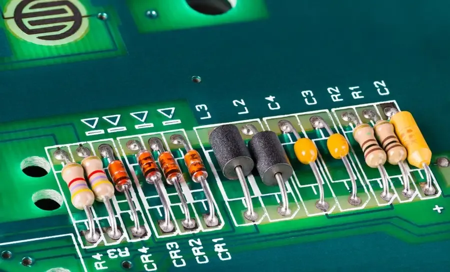
15 ohm resistors are frequently used for current limiting, particularly in LED circuits, where they control the current to prevent damage to the LED. They also function as pull-up or pull-down resistors in digital logic circuits, setting default signal states. Additionally, they can be found in audio circuits for impedance matching and signal conditioning. - How can I identify a 15 ohm resistor in a circuit?
Physically, a 15 ohm resistor is often identified by its color code. The standard color band sequence for a 15 ohm resistor with 1% tolerance is typically Brown, Green, Black, Golden, Brown. In circuit diagrams, it's labeled with the resistance value (15Ω or 15R). - How can I determine if a 15 ohm resistor is faulty?
A faulty resistor can manifest in several ways: it may be visibly damaged, discolored, or burnt. Functionally, its resistance might deviate significantly from the specified 15 ohms. You can test it using a multimeter set to measure resistance. An open resistor will show infinite resistance, and a shorted resistor would read close to zero ohms. - What are the common power ratings for a 15 ohm resistor?
15 ohm resistors come in various power ratings, from low-power 1/8W and 1/4W for simple circuits to higher power ratings like 1W, 2W, or even 5W and above, for handling more current and preventing overheating. The appropriate wattage rating depends on the power the resistor is expected to dissipate. - Can a 15 ohm resistor be used as a load resistor?
Yes, a 15 ohm resistor can be used as a load resistor in power circuits. In such instances, its purpose is to provide a defined load to the power source, allowing you to test the source's capacity. The key consideration here is ensuring the resistor's power rating is sufficient to dissipate the heat generated by the current flowing through it without failing. - What is the tolerance of a 15 ohm resistor and how does it impact circuit design?
The tolerance indicates the allowable deviation of the actual resistance from the specified value. A 1% tolerance resistor will have a resistance within ±1% of 15 ohms, while a 5% tolerance resistor will be within ±5% of 15 ohms. Precision applications require low tolerances, while general-purpose circuits can often use higher tolerance values. When precise resistance is critical for your application, opting for a lower tolerance resistor is essential.
The 15 ohm resistor, though small, holds considerable power in the world of electronics. From controlling the brightness of LEDs to balancing current in complex circuits, this simple component plays a critical role. By understanding its properties, variations, and applications, you can confidently integrate the 15 ohm resistor into your projects. When in doubt, always double-check the color codes, power ratings, and ensure that the 15 ohm resistor serves its purpose efficiently. This will ensure the longevity and proper function of your electronic creations.