Understanding the 180 Ohm Resistor: Types, Uses, and Selection Guide
In the realm of electronics, the humble resistor plays a crucial role in controlling current flow, much like traffic signals regulate the flow of cars in a city. One common value is the 180 ohm resistor, often encountered in various circuit designs, from hobbyist projects to sophisticated industrial equipment. This article will provide a comprehensive guide to understanding 180 ohm resistors, their types, applications, and selection criteria, and help you confidently integrate them into your next creation. Whether you are building a simple LED circuit or working on a more complex system, understanding the properties of a 180 ohm resistor is fundamental.
What is a 180 Ohm Resistor?
A 180 ohm resistor is a fundamental electronic component characterized by its ability to impede the flow of electrical current, providing a fixed resistance of 180 ohms. This passive two-terminal device plays a crucial role in controlling current and voltage within electronic circuits, ensuring the desired operation and performance of the overall system.
Types of 180 Ohm Resistors: A Detailed Comparison
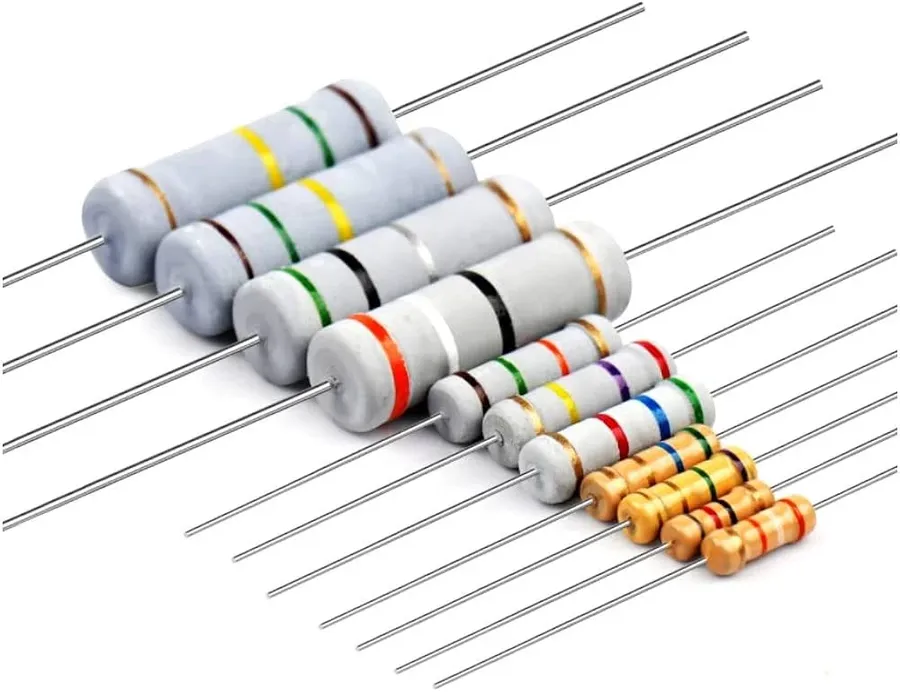
180 ohm resistors, while all providing the same nominal resistance, are manufactured using different technologies, resulting in varying characteristics that influence their suitability for different applications. The primary types include carbon composition, metal film, and surface mount (chip) resistors, each with distinct performance attributes related to accuracy, stability, and noise.
| Feature | Carbon Composition | Metal Film | Chip Resistor (SMD) |
|---|---|---|---|
| Tolerance | 5-20% | 1-5% | 0.1%-5% |
| Stability | Lower | Higher | Higher |
| Noise | Higher | Lower | Lower |
| Power Rating | Lower | Medium | Low-Medium |
| Size | Larger | Medium | Smallest |
| Cost | Lower | Medium | Medium-High |
| Applications | Vintage Equipment, High Surge | Precision circuits | Modern electronics, compact designs |
Understanding the characteristics of different 180 ohm resistor types is crucial for selecting the appropriate component for a specific application. This table provides a detailed comparison of carbon composition, metal film, and chip resistors, focusing on key parameters that influence their performance in electronic circuits.
| Feature | Carbon Composition | Metal Film | Chip Resistor (SMD) |
|---|---|---|---|
| Tolerance | 5-20% | 1-5% | 0.1%-5% |
| Stability | Lower | Higher | Higher |
| Noise | Higher | Lower | Lower |
| Power Rating | Lower | Medium | Low-Medium |
| Size | Larger | Medium | Smallest |
| Cost | Lower | Medium | Medium-High |
| Applications | Vintage Equipment, High Surge | Precision circuits | Modern electronics, compact designs |
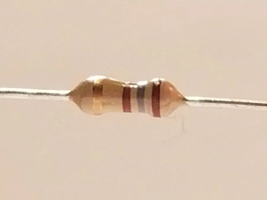
180 Ohm Resistor Color Code and Markings
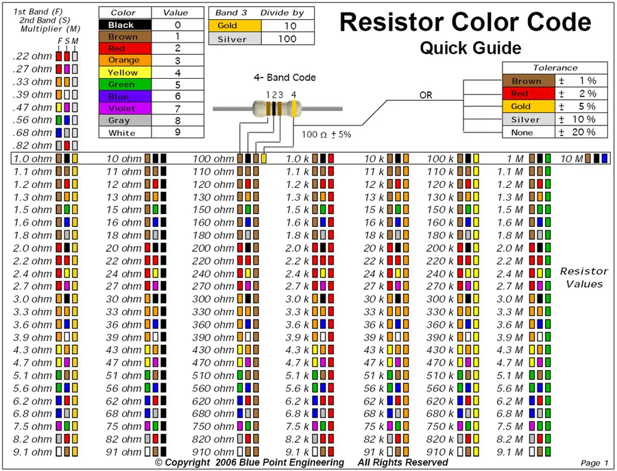
Resistors use color bands to indicate their resistance value and tolerance, with the 180 ohm resistor typically employing a series of bands. Understanding these color codes is crucial for identifying the resistor's specifications without needing a multimeter. Both 4-band and 5-band coding systems are common, though the 5-band provides greater precision.
| Band | Color | Digit (4-Band) | Digit (5-Band) | Multiplier | Tolerance |
|---|---|---|---|---|---|
| 1st Band | Brown | 1 | 1 | None | None |
| 2nd Band | Grey | 8 | 8 | None | None |
| 3rd Band | Brown | None | 0 | x 10 | None |
| 4th Band | Gold | x 0.1 | x 0.1 | None | 5% |
| 3rd Band(5-Band) | Black | None | 0 | None | None |
| 5th Band(5-Band) | Brown | None | None | None | 1% |
| 4th Band(4-Band) | Gold | None | None | None | 5% |
For a standard 180 ohm resistor with a 5% tolerance, the 4-band color code is typically: Brown (1st digit), Grey (2nd digit), Brown (multiplier of 10), and Gold (5% tolerance). A 5-band resistor with 1% tolerance would be: Brown, Grey, Black, Brown, and Brown. The first three bands in a 5-band system are for precise numerical values, and the fourth band is the multiplier, and the fifth band is for tolerance.
Common Applications of 180 Ohm Resistors
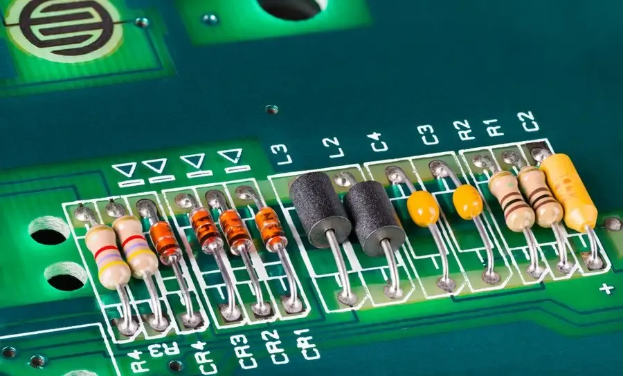
The 180 ohm resistor, a fundamental component in electronics, is frequently utilized for current limiting, voltage division, and signal conditioning across diverse electronic circuits. Its specific resistance value makes it particularly suitable for these applications, which are crucial for controlling current and signal levels within electronic systems.
- LED Circuits
180 ohm resistors are commonly employed to limit the current flowing through light-emitting diodes (LEDs), preventing damage and ensuring optimal brightness. By Ohm's Law, a 180-ohm resistor in series with an LED and a voltage source will control the current based on the voltage drop across the LED. For instance, using a 5V source, a typical LED with a 2V forward voltage will have the remaining 3V across the resistor. This allows for a current calculation and LED protection. The precise current can be derived using Ohm’s Law, V=IR. - Pull-up and Pull-down Resistors
In digital logic circuits, 180 ohm resistors act as pull-up or pull-down resistors to establish defined logic levels for input pins that might otherwise float. When the switch is open, the input is connected to the reference voltage (e.g., VCC) through the resistor, effectively ‘pulling’ the input HIGH. Conversely, pull-down resistors will cause the input to register a LOW state. This ensures reliable detection of HIGH and LOW signals and avoids indeterminate states that could cause issues. - Amplifier Bias Circuits
180 ohm resistors are often used in the bias network of amplifier circuits, especially those using transistors and op-amps, providing a stable operating point. They provide the necessary base current to the transistor which sets the amplifier's operating point and provides stability. This ensures that the amplifier functions within its linear region, producing high-quality amplification of the input signal. The value is important in setting the gain and impedance. - Signal Conditioning
180 ohm resistors are used for attenuation, impedance matching, and filtering of signals. They are part of resistor networks that help in signal shaping, reduction, or modification to match the impedance of a transmission line which prevents signal reflection. A precise value such as 180 ohms can be important for signal integrity. The resistor can be used to create a voltage divider for adjusting signal levels
Choosing the Right 180 Ohm Resistor for Your Project

Selecting the appropriate 180 ohm resistor for a project requires careful consideration of several factors to ensure optimal circuit performance and reliability. The key elements include resistor type, power rating (wattage), tolerance, and the operating environment. Understanding these parameters will enable informed decisions that are well-suited to specific application needs.
Here’s a detailed look at these considerations:
- Resistor Type
Choose the resistor type based on the required accuracy, stability, and noise characteristics. Metal film resistors offer better precision and stability compared to carbon composition resistors, making them suitable for critical applications. Chip resistors (SMD) are ideal for compact, modern designs. - Power Rating (Wattage)
The resistor's power rating must be sufficient to handle the power it will dissipate as heat. Use Ohm's Law and the expected voltage and current to calculate the expected power dissipation (P = I²R or P=V²/R). Always select a resistor with a power rating well above the calculated dissipation to ensure reliable operation and prevent overheating. It is advisable to use a safety factor of at least 2 for the power rating. For instance, a 1/4W 180 ohm resistor may be adequate for low power LED circuits, while more demanding applications may require 1/2W, 1W, or even higher power ratings. - Tolerance
Tolerance defines the allowable deviation of the actual resistance from the nominal value (180 ohms in this case). Tighter tolerance resistors, such as 1% or 0.1%, provide greater precision but come at a higher cost. A 5% tolerance is acceptable for general use or non-critical applications. Applications requiring precise current or voltage control, such as instrumentation amplifiers, would be benefit from using 1% or lower tolerance resistors. - Operating Environment
The operating temperature, humidity, and physical stresses may impact resistor selection. Consider the resistor’s temperature coefficient of resistance (TCR) especially if the application operates in wide temperature variations. For instance, in applications exposed to high temperatures, a high temperature rated resistor will provide stability. - Physical Size and Mounting
Ensure the resistor's physical size and mounting style (through-hole or surface-mount) is compatible with the circuit board and the assembly process. Through-hole resistors are easier to handle for prototypes, while surface mount devices (SMD) are standard for mass production and compact designs. Make sure the chosen SMD resistor has the correct physical size as designated by its packaging (e.g. 0603, 0805, etc.).
180 Ohm Resistor Frequently Asked Questions
This section addresses common queries about 180 ohm resistors, providing concise answers to help clarify their properties and usage. Understanding these frequently asked questions is essential for anyone working with electronic circuits.
- What are the color bands for a 180 ohm resistor?
For a standard 4-band 180 ohm resistor, the color bands are typically brown, gray, brown, and gold. The first band (brown) represents 1, the second band (gray) represents 8, and the third band (brown) is the multiplier (10^1), resulting in 18 x 10^1 ohms or 180 ohms. The gold band represents a 5% tolerance. For 5-band resistors, an additional band is used to achieve greater precision. - What is the standard color code for a 180 ohm resistor with a 1% tolerance?
A 180 ohm resistor with 1% tolerance would typically have a 5-band color code. The color bands will be brown, gray, black, black, and brown. The first three bands (brown, gray, black) are the significant digits (1, 8, 0), the fourth band is the multiplier (10^0), and the fifth band (brown) denotes the 1% tolerance. - What is the color code for a 680 ohm resistor?
The color code for a 680 ohm resistor is typically blue, grey, brown, and gold (for 5% tolerance). The first band (blue) represents 6, the second band (grey) represents 8, the third band (brown) is the multiplier (10^1), resulting in 68 x 10^1 ohms or 680 ohms. The gold band represents a 5% tolerance. - What is the color code for a 1.8 K ohm resistor?
For a 1.8 kΩ resistor, the color code would typically be brown, gray, red, and gold (for 5% tolerance). The first band (brown) represents 1, the second band (grey) represents 8, and the third band (red) is the multiplier (10^2), resulting in 18 x 10^2 or 1800 ohms (1.8kΩ). The gold band represents a 5% tolerance. - What does the tolerance of a 180 ohm resistor mean?
Tolerance indicates the acceptable variation in the actual resistance value compared to its nominal value. A 5% tolerance on a 180 ohm resistor means the actual resistance can be between 171 ohms and 189 ohms (180 ohms ± 5%). Lower tolerance resistors offer more precise resistance values. - Can I use a different resistor if I don't have a 180 ohm?
While it's generally best to use the specified resistance, in some cases, a nearby value can be substituted. If replacing a 180 ohm resistor you should try to stay within a ±10% variance of the original component. It's crucial to consider the circuit's sensitivity to resistance variations before making a substitution, especially in sensitive electronic circuits where the performance could be compromised with any significant changes. - What are common applications for a 180 ohm resistor?
180 ohm resistors are commonly used for current limiting in LED circuits, as pull-up or pull-down resistors in digital circuits, and for signal conditioning and biasing in amplifiers and other analog circuits. They are chosen for their appropriate resistance in these applications and wide availability.
Practical Tips and Best Practices for Using 180 Ohm Resistors
Proper handling and usage of 180 ohm resistors are crucial for ensuring circuit reliability and performance. This section provides practical tips for soldering, breadboarding, handling, and verifying the condition of these essential components.
- Soldering 180 Ohm Resistors
When soldering, ensure the resistor leads are clean and the soldering iron is at the correct temperature to avoid thermal damage. Apply solder quickly and evenly to create a strong and reliable connection. Avoid excessive heat and prolonged exposure which can change the resistor's value or damage its internal structure. Use flux to improve solder flow and adhesion, and if using lead-free solder, remember it typically requires a higher temperature. - Breadboarding 180 Ohm Resistors
When using a breadboard, ensure the resistor leads are fully inserted into the appropriate holes to create a good electrical contact. Avoid bending or twisting the leads excessively to prevent damage. Check the connection by gently tugging each resistor lead to verify mechanical connection. Use a digital multimeter to confirm circuit connectivity once all components are placed on the breadboard. - Handling 180 Ohm Resistors
Resistors, while robust, can be damaged by excessive force or environmental factors. Store resistors in a dry, non-corrosive environment and avoid physical stress. Do not bend resistor leads excessively and avoid contact with corrosive materials. Electrostatic discharge can also affect sensitive resistors, so use ESD-safe practices when handling them, particularly chip resistors. - Checking 180 Ohm Resistor Value
Before incorporating a resistor into a circuit, it's essential to verify its resistance value. Use a digital multimeter set to the resistance measurement mode (Ohms - Ω). Connect the multimeter's probes to each end of the resistor, ensuring a good electrical contact. Compare the measured value against the marked or color-coded resistance value. Be aware of the tolerance, and that a slight variance in resistance within that tolerance is expected. This ensures that the circuit functions as expected and helps in troubleshooting. - Checking Resistor Condition
Visual inspection can reveal physical damage, but does not always reveal changes to value. Check resistors for cracks, burns, or other signs of damage before use. The multimeter can also be used to check for a 'open' resistor. If a reading of 'OL' or a very high resistance is displayed, the resistor is likely faulty. Always replace damaged or questionable resistors to ensure circuit reliability and proper functioning.
Understanding 180 ohm resistors is essential for anyone working with electronics. From choosing the right type, like a precise metal film 180 ohm resistor, to correctly interpreting their color codes, this article has provided a foundation for successful circuit design. Remember to carefully select your resistors based on your project’s requirements, consider power dissipation and precision, and always double-check connections for reliable operation. By using the information provided, users can confidently and effectively use 180 ohm resistors in various electronic applications, and explore future innovative project design.