Understanding the 1uF Capacitor: Uses, Types, and Applications
In the realm of electronics, the 1uF capacitor is a fundamental component, akin to a tiny rechargeable battery. [1uf] Its size may be small, but its role in smoothing power, storing energy, and filtering signals is crucial in countless devices. This article delves into the world of 1uF capacitors, exploring its various types, applications, and how they operate within our tech-driven world.
What is a 1uF Capacitor?
A 1uF capacitor, where 'uF' stands for microfarad, is an electronic component designed to store electrical energy in an electric field. The farad (F) is the base unit of capacitance, representing the ability of a component to store charge; a 1uF capacitor possesses one millionth (10^-6) of a farad of capacitance. Capacitors are fundamental building blocks in electronic circuits, used for various functions including filtering, energy storage, and timing.
Ceramic capacitors, particularly in the 1uF (microfarad) value, are ubiquitous in modern electronics due to their advantageous characteristics such as non-polarity and suitability for high-frequency applications. Their construction and material properties allow for stable performance across a wide range of conditions, making them a reliable choice for many circuit designs.
- Non-Polarity
Unlike electrolytic capacitors, ceramic capacitors are non-polarized, meaning they can be connected in a circuit in either direction without affecting performance or risking damage. This simplifies circuit design and assembly. - High-Frequency Performance
Ceramic capacitors exhibit low equivalent series resistance (ESR) and low equivalent series inductance (ESL), which are key for stable operation in high-frequency circuits. This makes them ideal for applications where rapid changes in current or voltage are common. - Construction and Materials
These capacitors are typically constructed using ceramic dielectric materials, such as barium titanate, which are sandwiched between metallic electrodes. The ceramic composition directly impacts the capacitor's properties, like temperature and voltage coefficient. - Common Applications
Ceramic 1uF capacitors are frequently used in decoupling circuits, filtering applications, and timing circuits due to their ability to handle fast transients and their compact size.
| Property | Description |
|---|---|
| Capacitance Range | Typically from a few picofarads (pF) to several microfarads (uF) |
| Voltage Rating | Available in a wide range, from a few volts to several kilovolts, depending on the dielectric material and construction. |
| Temperature Stability | Varies depending on the type of ceramic used, from relatively stable (NP0/COG) to less stable (X7R, Y5V). |
| Tolerance | Can vary from +/- 1% to +/- 20%, depending on the application requirements and capacitor manufacturing process. |
| ESR | Low, typically less than 1 Ohm. |
| ESL | Low, in the nanohenry range. |
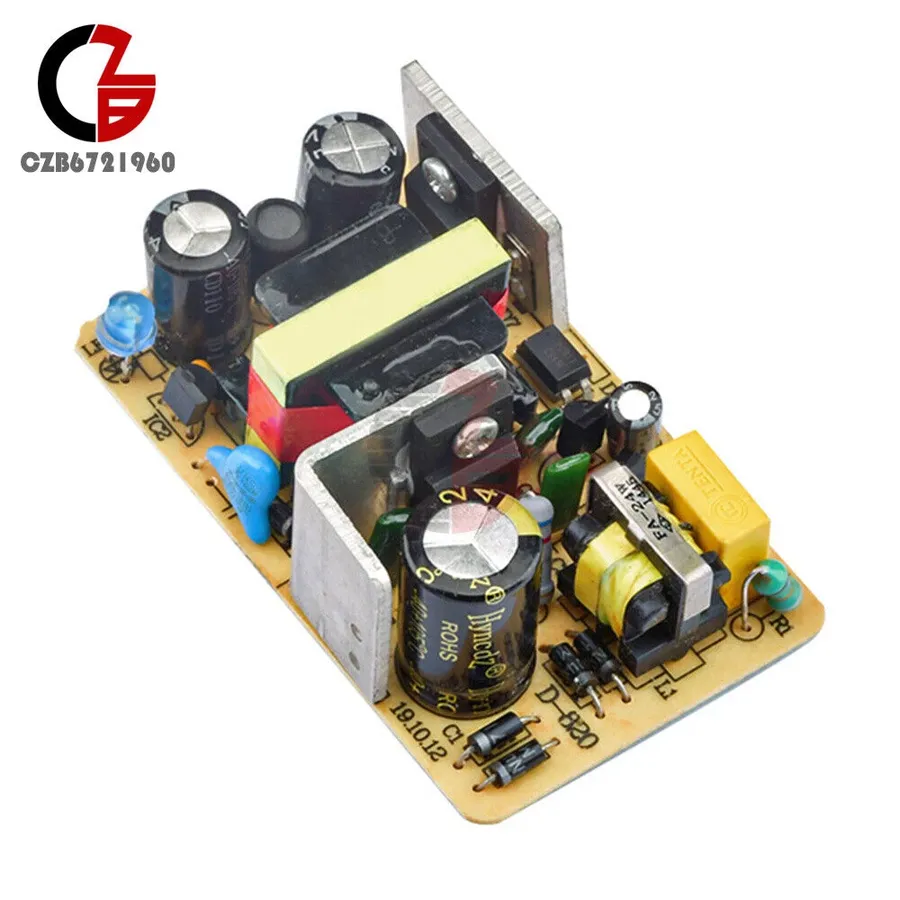
In power supply circuits, 1uF capacitors play a crucial role in smoothing the DC output by mitigating ripple and noise. These capacitors act as temporary energy storage devices, charging when the voltage is high and discharging when the voltage drops, effectively stabilizing the power supply.
Specifically, when a rectifier converts AC to DC, the resulting output is not a perfect straight line but rather a pulsating DC with a superimposed AC component known as ripple. A 1uF capacitor, connected in parallel with the load, helps to smooth out this ripple. When the rectifier output voltage rises, the capacitor charges, storing energy. When the rectifier voltage falls, the capacitor releases the stored energy, thereby keeping the voltage relatively stable at the load. This helps in reducing unwanted voltage fluctuations and noise in the power supply, leading to a more stable and reliable operation of electronic devices.
| Parameter | Description | Impact on Smoothing |
|---|---|---|
| Capacitance | 1uF (microfarad) | Determines the amount of charge stored. Higher capacitance values generally provide better smoothing for low frequency ripple. |
| ESR (Equivalent Series Resistance) | Low | Lower ESR values allow for better ripple handling and faster charge/discharge times, leading to more effective smoothing. Higher ESR results in heat dissipation during charging and discharging which impacts efficiency. |
| Voltage Rating | Specific to the application | Must exceed the maximum voltage in the circuit to avoid capacitor failure, which can impact smoothing performance and safety. |
| Frequency Range | Low to Medium Frequency | Effective in filtering out low-to-medium frequency ripple found in typical power supply circuits. For higher frequencies other component may be needed. |
Types of 1uF Capacitors
1uF capacitors are essential components in electronic circuits, and they are available in several types, each with its own set of characteristics, advantages, and disadvantages. Understanding these differences is crucial for selecting the right capacitor for a specific application. The primary types of 1uF capacitors include ceramic, electrolytic, and film capacitors. Each type's construction and materials dictate its performance characteristics, such as temperature stability, frequency response, and tolerance.
| Capacitor Type | Material | Polarity | Pros | Cons | Typical Applications |
|---|---|---|---|---|---|
| Ceramic | Ceramic Dielectric | Non-Polarized | Low Cost, High Frequency Performance, Small Size | Lower Capacitance Value, Temperature Dependence | Bypass, Coupling, High-Frequency Circuits |
| Electrolytic | Aluminum or Tantalum with Electrolyte | Polarized | High Capacitance Value, Low Cost | Higher Equivalent Series Resistance (ESR), Limited Frequency Range, Aging | Power Supply Filtering, Decoupling |
| Film | Polyester, Polypropylene, or other Dielectric Films | Non-Polarized | High Precision, Low ESR, Good Stability, High Voltage Applications | Larger Size, Higher Cost | Audio Circuits, Precision Timing Circuits, High Voltage Applications |
Ceramic Capacitors
Ceramic 1uF capacitors, characterized by their non-polarized nature and compact size, are widely used in high-frequency circuits. Constructed using ceramic dielectric materials, they exhibit excellent performance in applications where high-frequency response and stability are required, such as in bypass and coupling circuits. Their non-polar nature means they can be inserted into a circuit in either direction without concern for polarity. However, their capacitance can be affected by temperature changes and they generally offer a lower overall capacitance range compared to other types.
Electrolytic Capacitors
Electrolytic 1uF capacitors are distinguished by their polarized nature, requiring proper orientation in circuits, and are ideal for applications requiring high capacitance values. These capacitors are typically made with an aluminum or tantalum electrode and an electrolyte, enabling them to achieve higher capacitance in smaller physical sizes. However, they have higher equivalent series resistance (ESR) and are generally not suitable for high-frequency applications. They are widely used in power supply filtering and decoupling, where higher capacitance is needed to smooth out voltage fluctuations.
Film Capacitors
Film 1uF capacitors are known for their high precision, low ESR, and good stability, making them suitable for applications requiring tight tolerances and high voltage. They are constructed using thin layers of dielectric films such as polyester, polypropylene or other advanced materials. Due to their robust construction, film capacitors are excellent for precision timing circuits, audio circuits, and high voltage applications. Despite their superior performance, they tend to be larger and more expensive compared to ceramic or electrolytic capacitors.
Electrolytic capacitors, including 1uF variants, are characterized by their polarized nature, meaning they must be connected in a circuit with the correct polarity (positive and negative terminals). They typically offer higher capacitance values compared to ceramic or film capacitors, making them suitable for applications where larger charge storage is needed but are limited in high frequency applications.
A 1uF electrolytic capacitor utilizes a metallic anode, an electrolyte (which can be a liquid or a solid), and a cathode. The dielectric layer is formed electrochemically, resulting in a thin layer capable of storing a significant charge in a relatively small package. However, this electrochemical formation process also contributes to their polarized nature and performance characteristics.
| Characteristic | Electrolytic 1uF Capacitor | Ceramic 1uF Capacitor | Film 1uF Capacitor |
|---|---|---|---|
| Polarity | Polarized | Non-Polarized | Non-Polarized |
| Capacitance Range | High | Low to Medium | Medium to High |
| Frequency Response | Limited | Excellent | Good to Excellent |
| Tolerance | High | Medium to High | Low to Medium |
| Cost | Low | Low to Medium | Medium to High |
| Typical Applications | Power supply filtering, decoupling | High-frequency circuits, bypass | Precision timing, audio circuits |
Given their limitations in high-frequency performance, electrolytic capacitors are generally avoided in high-speed digital circuits or radio-frequency applications. Their primary usage is in applications that benefit from their ability to hold a relatively large charge and do not require high speed response. The polarity of the capacitor must be observed during installation to avoid damage.
- Advantages of Electrolytic 1uF Capacitors:
High capacitance-to-volume ratio allows for significant charge storage in a small size. They are also cost effective in high capacitance applications. - Disadvantages of Electrolytic 1uF Capacitors:
They exhibit higher equivalent series resistance (ESR) compared to ceramic or film capacitors, leading to higher power dissipation. Limited frequency response makes them unsuitable for high-speed circuits. Electrolytic capacitors also have a limited lifespan, especially at high temperatures, and are polarity sensitive.
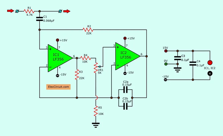
1uF capacitors play a crucial role in signal filtering, effectively removing unwanted frequencies and noise from both audio and radio frequency (RF) circuits. This capability is essential for maintaining signal integrity and ensuring clear, accurate transmission or reproduction of signals.
In audio circuits, 1uF capacitors are frequently employed to eliminate low-frequency hum or hiss, which can degrade audio quality. The capacitor acts as a high-pass filter, blocking the lower frequencies while allowing higher-frequency audio signals to pass through. This ensures that only the intended frequencies reach the amplifier or speaker.
In RF circuits, 1uF capacitors are used to filter out noise and interference, such as electromagnetic interference (EMI). By selectively allowing the desired RF signals to pass while attenuating unwanted noise, these capacitors contribute to stable and reliable communication. In these applications, the capacitor may act as a high-pass or low-pass filter, depending on its position in the circuit.
| Application | Frequency Range | Filtering Mechanism | Benefits |
|---|---|---|---|
| Audio Circuits | 20 Hz - 20 kHz | High-pass filter, blocks low frequencies (hum/hiss) | Improved audio clarity, reduced noise floor |
| RF Circuits | kHz - GHz | High-pass or low-pass filter, attenuates interference and unwanted signals | Stable communications, minimizes interference |
The specific use of a 1uF capacitor in a signal filtering application depends on the impedance of the circuit, the frequencies of the signal that need to be filtered and the type of filtering needed (high-pass, low-pass or band-pass). Understanding these parameters is critical when selecting the correct capacitor for the circuit.
Film capacitors, particularly in the 1uF range, stand out due to their construction which allows for higher voltage operation and tighter tolerances compared to other capacitor types. These capacitors utilize thin plastic films as the dielectric material, resulting in stable performance and low losses. Various film materials and construction methods cater to specific application needs.
| Characteristic | Polyester Film | Metalized Film | Polypropylene Film |
|---|---|---|---|
| Temperature Stability | Good | Good | Excellent |
| Tolerance | Medium | Medium | High |
| Voltage Handling | High | High | Very High |
| Self-healing | No | Yes | No |
| Cost | Low | Medium | High |
| Typical Applications | General purpose, coupling, decoupling | Filtering, high-frequency applications | High-voltage, precision circuits |
Film capacitors are constructed in a variety of ways. Some have electrodes made of thin metal foil, while others have electrodes deposited directly on the film using a metallization process. Metalized film capacitors offer self-healing properties which can be an advantage, as a localized breakdown in the dielectric can result in the thin metal layer vaporizing away from the fault point and therefore 'healing' the defect to maintain the capacitor's performance.
1uF Capacitor Applications in Electronics
1uF capacitors, characterized by their ability to store a microfarad of electrical charge, find widespread use across numerous electronic applications. These applications leverage the capacitor's fundamental property to store energy and control electrical signals in diverse ways, including smoothing power supplies, filtering unwanted frequencies, coupling and decoupling signals, and enabling timing circuits.
- Power Supply Smoothing
In power supply circuits, 1uF capacitors are essential for reducing ripple and noise, ensuring a stable DC output. These capacitors store energy when the voltage is high and release it when the voltage dips, thereby smoothing out fluctuations. - Signal Filtering
1uF capacitors are used to filter unwanted frequencies in audio and radio frequency circuits. By selectively allowing certain frequencies to pass while blocking others, they play a vital role in signal processing and noise reduction. - Coupling and Decoupling
In circuit design, 1uF capacitors are used for coupling signals between different stages, allowing AC signals to pass while blocking DC. They also act as decoupling capacitors, preventing noise from affecting sensitive circuit components by shunting it to ground. - Timing Circuits
1uF capacitors also play a role in various timing circuits. Combined with resistors, they allow the design of circuits that can accurately control timing functions, such as generating a delay or oscillation. The time constant (τ) of an RC circuit with a 1uF capacitor is equal to the capacitance value multiplied by the resistance, influencing the speed of charge and discharge.
| Application | Function | Mechanism |
|---|---|---|
| Power Supply Smoothing | Reduces ripple and noise | Stores and releases energy to maintain constant DC output |
| Signal Filtering | Removes unwanted frequencies | Allows certain frequencies to pass while blocking others |
| Coupling | Transfers AC signals | Blocks DC while passing AC signals between circuit stages |
| Decoupling | Isolates sensitive components from noise | Shunts noise to ground |
| Timing Circuits | Controls circuit timing | Charges and discharges to generate delays |
Power Supply Smoothing
In power supply circuits, the 1uF capacitor plays a crucial role in mitigating voltage fluctuations, also known as ripple, ensuring a stable and consistent DC output. These fluctuations are typically a result of AC-to-DC conversion processes. A capacitor with 1uF value acts as a buffer by storing energy when the voltage is at its peak and releasing it when voltage dips, thus effectively smoothing the DC output.
Signal Filtering
The 1uF capacitor is integral to signal filtering across various applications such as audio and RF (Radio Frequency) circuits. They operate on the principle of capacitive reactance which is inversely proportional to the frequency of the signal. This characteristic enables them to block or pass specific frequencies, thereby filtering out noise and unwanted frequencies while ensuring signal clarity. They are primarily used to implement low pass filters which permit low frequency signals to pass while blocking high frequency signals.
Coupling and Decoupling
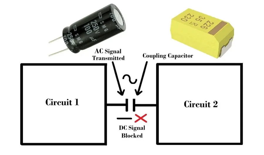
1uF capacitors are essential in both coupling and decoupling roles within complex electronic circuits. As coupling capacitors, they facilitate the transfer of AC signals from one circuit stage to another while blocking any DC components. This ensures that the signal is passed without affecting the bias of next stage. As decoupling capacitors, they mitigate noise by shunting it to the ground. This stabilizes the power supply by preventing parasitic noise from affecting sensitive ICs, especially at high frequencies, thereby maintaining the circuit's integrity.
1uF capacitors play crucial roles in both coupling and decoupling within electronic circuits. These seemingly opposite functions are vital for ensuring signal integrity and stable operation. Coupling allows AC signals to pass between stages while blocking DC, whereas decoupling provides a low-impedance path to ground for unwanted noise.
- Coupling Explained
In coupling, a 1uF capacitor facilitates the transfer of AC signals from one circuit stage to another. The capacitor blocks any DC offset that might exist between the stages, preventing unwanted DC bias from interfering with the signal. This is particularly useful in audio circuits where you want to pass the audio signal but block any DC components. - Decoupling Explained
Decoupling, also known as bypass, utilizes a 1uF capacitor to shunt high-frequency noise to ground. Placed close to the power pins of integrated circuits (ICs), the capacitor acts as a local energy reservoir and a low impedance path for AC noise. This minimizes the impact of transient voltage drops and high-frequency noise on the IC's operation. By providing a low-impedance path, the decoupling capacitor helps ensure stable power supply and reduces the chance of unwanted oscillations or glitches. - Coupling vs. Decoupling
While both coupling and decoupling use capacitors, their purpose and placement are different. Coupling capacitors are typically placed in the signal path between stages, while decoupling capacitors are placed between power pins and ground to filter power supply noise.
| Feature | Coupling | Decoupling |
|---|---|---|
| Purpose | Pass AC signal, block DC | Filter power supply noise, provide low impedance path to ground |
| Placement | In signal path between circuit stages | Close to power pins of ICs, between power and ground |
| Effect | Transfers AC signal, prevents DC bias | Stabilizes power supply, reduces noise |
1uF Capacitor Markings and Codes
Understanding the markings and codes on 1uF capacitors is crucial for proper identification and application. These markings convey essential information about the capacitor's value, tolerance, voltage rating, and other critical specifications, ensuring correct selection and usage in electronic circuits.
| Marking Type | Description | Example |
|---|---|---|
| Numeric Value | Directly indicates capacitance value in microfarads (uF) or picofarads (pF), sometimes with multipliers | 1uF, 105 (for 1uF), 104 (for 100nF/0.1uF) |
| Letter Codes | Typically used for tolerance or voltage ratings | J (5% Tolerance), K (10% Tolerance), X (Temperature Coefficient) |
| Voltage Rating | Indicates the maximum voltage the capacitor can safely withstand | 25V, 50V, 100V |
| Manufacturer's Logo | Identifies the capacitor's manufacturer | Various logos, usually small in size |
| Date Code | Indicates the date the capacitor was manufactured | Various formats depending on the manufacturer (e.g., YYWW format) |
| SMD Case Code | For surface mount devices, specifies physical dimensions. | 0603, 0805, 1206 etc. |
1uF Capacitors and Treble Bleed Circuits
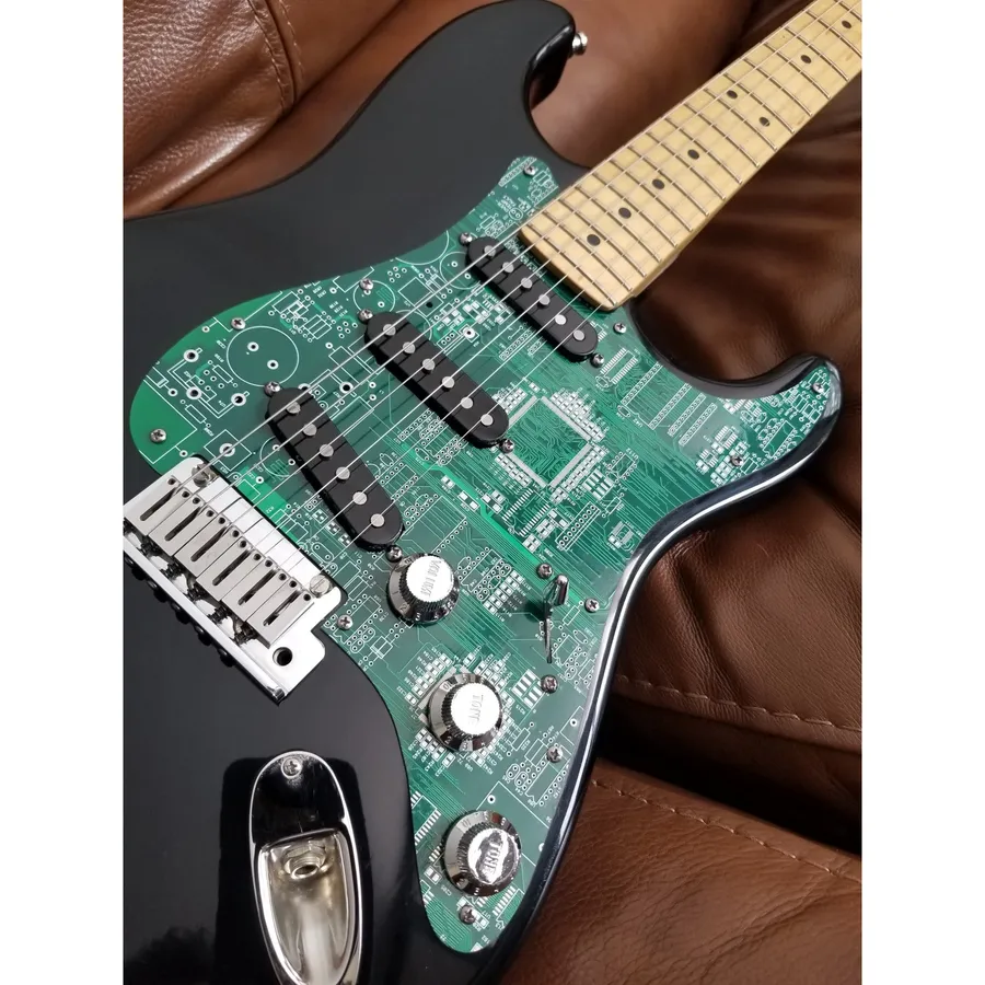
A 1uF capacitor plays a critical role in treble bleed circuits, particularly in audio equipment like guitars, by preserving high-frequency content at lower volume settings. Without this capacitor, the high frequencies would be disproportionately attenuated as the volume is decreased, resulting in a loss of clarity and brilliance, a phenomenon often described as 'muddy' or 'dull' sound.
The essence of a treble bleed circuit is to counteract the tendency of potentiometers (volume controls) to act as low-pass filters at lower resistances. As the volume pot is turned down, its resistance decreases which would naturally attenuate the higher frequencies more than the lower frequencies. By introducing a capacitor, typically a 1uF in this application, in parallel with a resistor across the input and output of the volume pot, a high-pass filter is created that allows the high frequencies to pass more readily than lower ones. This effectively compensates for the pot’s action, leading to a more balanced frequency response across the entire range of volume control.
The specific value of 1uF is chosen to effectively boost the higher frequencies within the audible range that are typically attenuated by the volume pot. Values greater or less than 1uF may shift the frequency at which the bleed occurs and may lead to unbalanced sound.
The implementation is relatively simple. In most common applications, a 1uF capacitor, usually a film capacitor given its tonal characteristics, is connected in parallel with a resistor of a value commonly found within the 100k-150k ohm range. This entire subcircuit is then connected between the input and output terminals of the volume pot in the audio circuit. This creates a frequency dependent shunt path around the volume control.
In summary, the strategic use of a 1uF capacitor in treble bleed circuits is indispensable for maintaining the full spectrum of sound, particularly the high frequencies, even at lower volume levels. This is why the 1uF capacitor is so frequently used for this application.
Frequently Asked Questions About 1uF Capacitors
This section addresses common queries about 1uF capacitors, clarifying their meaning, value conversion, identification, and representation.
- What does 1uF mean on a capacitor?
1uF signifies a capacitance of one microfarad. A farad (F) is the base unit of capacitance, representing a capacitor's ability to store electrical charge. A microfarad (uF) is one millionth of a farad (10^-6 F). Thus, a 1uF capacitor can store a specific amount of charge, that is one millionth of a farad, for a given voltage, a crucial parameter in electronic circuit design. - What is the equivalent of 1uF in picofarads (pF)?
One microfarad (1uF) is equal to one million picofarads (pF). Since 1uF is 10^-6 F and 1pF is 10^-12 F, converting 1uF to pF involves multiplying by 10^6 (1,000,000). Therefore, 1uF = 1,000,000pF, this conversion is critical when dealing with circuits that involve small signal and high frequency characteristics. - How do I identify the value of a 1uF capacitor?
The method for identifying a 1uF capacitor's value varies depending on its type. For surface mount devices (SMD), the marking will typically consist of a numerical or alpha-numeric code, requiring datasheets or conversion charts for interpretation. Leaded components will be more direct with 1uF, or, 1.0uF, as well as with the voltage and temperature ratings marked, typically. The method to read capacitor codes will be discussed in detail in the section '1uF Capacitor Markings and Codes'. - What are typical voltage ratings for 1uF capacitors?
1uF capacitors can come with different voltage ratings depending on their construction and intended applications. Ceramic capacitors might have ratings from a few volts to hundreds of volts, while electrolytic ones can range from a few volts to several hundred volts. Film capacitors are available for even higher voltages, potentially several thousand volts, and it is critical to select one with a rating exceeding the maximum expected voltage in a circuit to ensure reliable operation and to prevent the component from failing. - Can 1uF capacitors be used in high-frequency applications?
The suitability of a 1uF capacitor for high-frequency applications is heavily dependent on its type. Ceramic capacitors, specifically multi-layer ceramic capacitors (MLCCs), are very well suited because of their low equivalent series resistance (ESR) and equivalent series inductance (ESL). Electrolytic capacitors are not well-suited for high frequencies because of their higher ESR and ESL, and other effects that influence their impedance, leading to non-ideal behavior. Film capacitors often fall in the middle in terms of frequency handling, and are not as performant in high frequency applications compared to MLCCs. - Why are 1uF capacitors used for decoupling?
1uF capacitors are commonly used for decoupling in electronic circuits to stabilize power supplies and to mitigate noise propagation. Placed close to the active integrated circuit, they act as a local charge reservoir, providing the instantaneous current that the circuit requires, and reducing voltage fluctuations. This application is very important in digital circuits, where rapid transitions in logic states can create significant spikes in current demands. - What does a '105' marking mean on a capacitor?
The marking '105' on a capacitor is a code to determine its capacitance value. The first two digits represent the significant figures (10) and the third digit represents the multiplier, which is a power of ten (5 in this case), and the resulting units are in picofarads (pF). So, 10 * 10^5 pF = 1,000,000 pF = 1uF. Such numerical codes are often used on ceramic capacitors.
Selecting the Right 1uF Capacitor
Choosing the appropriate 1uF capacitor is crucial for optimal circuit performance and reliability. The selection process should consider several key electrical and environmental parameters. Incorrect selection can lead to reduced performance, premature failure, or even damage to other components.
| Parameter | Description | Considerations |
|---|---|---|
| Voltage Rating | The maximum voltage the capacitor can withstand without damage. | Select a capacitor with a voltage rating significantly higher than the expected operating voltage to ensure safety and reliability. A commonly accepted derating factor is around 50-75%, i.e. a working voltage of 50% or 75% of the rated voltage. |
| Temperature Coefficient | How the capacitor's capacitance changes with temperature. | Consider the expected operating temperature range and choose a capacitor with a suitable temperature coefficient. For high temperature environment, choose a material with less temperature coefficient, such as COG or NPO for ceramic capacitors. |
| Capacitance Tolerance | The allowable deviation from the nominal 1uF capacitance. | Choose a tolerance that meets the specific requirements of the circuit. For timing applications, lower tolerance capacitors are preferred. High tolerance can cause unpredictable results. Common tolerances include ±5%, ±10%, ±20%. |
| Equivalent Series Resistance (ESR) | The inherent resistance within the capacitor. | For high-frequency circuits, minimize ESR. Electrolytic capacitors typically have higher ESR than ceramic or film capacitors. |
| Leakage Current | The small current that flows through the dielectric material when a voltage is applied. | Choose a capacitor with low leakage current for applications where minimal energy loss is critical. Electrolytic capacitors usually have a higher leakage current than other types. |
| Physical Size and Form Factor | The physical dimensions and packaging of the capacitor. | Ensure the capacitor will physically fit within the available space on the PCB or within the enclosure and choose appropriate mounting method. |
| Dielectric Material | The insulating material used in the capacitor. | Different dielectrics have different performance characteristics. Ceramic capacitors are suitable for high frequency, while electrolytic types are used for high capacitance values. |
Troubleshooting and Testing 1uF Capacitors
Ensuring the proper function of a 1uF capacitor is crucial for circuit reliability. This section outlines methods for testing and identifying common failure modes of 1uF capacitors, using a multimeter and other techniques.
- Visual Inspection
Begin with a thorough visual check. Look for signs of damage such as cracks, bulging, leaks, or burnt marks on the capacitor body. These physical defects are strong indicators of failure. - Multimeter Capacitance Measurement
Use a multimeter with a capacitance measurement function to check the actual capacitance. The measured value should be close to the specified 1uF, typically within the tolerance range (e.g., ±5%, ±10%, or ±20%). A significant deviation from this value indicates a potential problem. - Equivalent Series Resistance (ESR) Check
For electrolytic capacitors, ESR is a vital parameter. An elevated ESR can lead to poor performance even if the capacitance is within range. Use an ESR meter for precise measurement, or estimate using a multimeter’s resistance function (though it's less accurate). - Leakage Current Measurement
If a capacitor is suspected of having excessive leakage, measure the current flowing through it with a DC voltage applied. This is particularly important for electrolytic capacitors. A higher than rated leakage current indicates degradation of the capacitor. - Testing in-circuit vs. out-of-circuit
In-circuit testing can be done using a multimeter, but it is often less accurate due to the influence of surrounding components. For the most accurate measurements, remove the capacitor from the circuit board before testing.
| Failure Mode | Symptoms | Causes | Testing Method |
|---|---|---|---|
| Open Circuit | No capacitance measurement, circuit not functioning. | Internal connection failure, physical damage. | Multimeter: Capacitance = 0. |
| Short Circuit | Extremely low or no resistance, potential damage to other components. | Internal dielectric breakdown, overvoltage. | Multimeter: Resistance ~ 0. |
| Capacitance Drift | Measured value significantly deviates from 1uF. | Aging, temperature variations. | Multimeter: Measure capacitance, compare to specified value. |
| Increased ESR | Poor ripple filtering, reduced performance. | Electrolyte degradation, aging. | ESR meter: Measure ESR. |
| Increased Leakage Current | Capacitor gets warm, short battery life. | Dielectric breakdown, contamination. | Multimeter: Measure leakage current. |
The 1uF capacitor, a seemingly simple component, is a workhorse in electronics. [1uf] Understanding its diverse types, applications, and importance is vital for anyone involved in electronics. From filtering and smoothing to timing and decoupling, the 1uF capacitor continues to play a key role in shaping the modern world of technology, and it's likely to remain a cornerstone in the electronics industry for the foreseeable future.