Unlocking Efficiency: Understanding and Utilizing PFC Capacitors
In our energy-dependent world, efficiency is key. Like a well-tuned engine, our electrical systems need to operate optimally. The unsung hero behind this is the power factor correction (PFC) capacitor, a small but mighty component that reduces reactive power, thereby improving efficiency and lowering energy costs. This article will delve into the workings, benefits, and practical aspects of using PFC capacitors, and how they impact our daily lives, both within industries and at home, paving the way to understanding how we can better manage our energy consumption.
What is a PFC Capacitor and Why is it Important?
A Power Factor Correction (PFC) capacitor is a crucial component in electrical systems designed to improve power factor, a measure of how effectively electrical power is being used. It addresses the issue of reactive power, which does not perform useful work but circulates in the system, increasing energy consumption and potentially causing inefficiencies. By counteracting reactive power, PFC capacitors reduce energy waste and lower operational costs.
At the heart of the matter lies the concept of power factor. A power factor of 1 (or 100%) indicates that all the power delivered to a load is used to perform work, while a power factor less than 1 signifies that some power is wasted as reactive power. Reactive power arises due to inductive loads like motors and transformers, where the current lags behind the voltage. PFC capacitors, acting as capacitive loads, introduce a leading current that cancels out the lagging current from inductive loads, thus improving the power factor.
The significance of power factor directly impacts energy consumption and costs. Utilities often penalize consumers with poor power factors because they must supply more current than required for the actual work being done. By using PFC capacitors, businesses and facilities can avoid these penalties and reduce electricity bills. Furthermore, improving power factor enhances system capacity by reducing the strain on the electrical network, prolonging the lifespan of electrical equipment and reducing the risk of failures.
How PFC Capacitors Work: The Technical Aspects
Power Factor Correction (PFC) capacitors are employed in electrical systems to improve power factor by counteracting the effects of inductive loads. These capacitors operate by supplying reactive power, thereby reducing the burden on the power grid and improving overall system efficiency. The core principle lies in the interaction between capacitance and inductance within an alternating current (AC) circuit.
In AC circuits, inductive loads like motors and transformers cause the current to lag behind the voltage, resulting in reactive power. This reactive power does not perform useful work, but it increases the total current in the system, leading to losses and inefficiencies. A PFC capacitor, when introduced into the circuit, acts as a source of leading current. This leading current is out of phase with the lagging current, and the two partially cancel each other out, reducing the net reactive power and improving the power factor.
The analogy to a mechanical system is helpful. Imagine a tug-of-war where one team (representing inductive loads) is pulling backward and another team (representing the supply) is pulling forward. The PFC capacitor acts like a third team, pulling forward and slightly ahead of the supply team, thereby balancing the backward pull of the inductive load. This results in a more efficient transfer of work, analogous to electrical system with high power factor
| Component | Effect on AC Circuit | Current Phase Relative to Voltage |
|---|---|---|
| Inductive Load (e.g., Motor) | Causes current to lag behind voltage | Lagging |
| PFC Capacitor | Causes current to lead the voltage | Leading |
Benefits of Using PFC Capacitors
Power Factor Correction (PFC) capacitors offer substantial benefits across economic, operational, and environmental dimensions. These capacitors are primarily used to mitigate the adverse effects of reactive power, leading to improved system efficiency and reduced costs. By addressing low power factors, PFC capacitors not only prevent financial penalties but also enhance the overall performance and longevity of electrical systems and equipment.
- Reduced Energy Costs
A primary benefit of PFC capacitors is the reduction in energy bills. Utility companies often impose penalties on consumers with low power factors due to the inefficient use of electrical power. PFC capacitors improve the power factor by supplying the necessary reactive power locally, thus decreasing the burden on the power grid and avoiding these penalties. - Improved Electrical System Efficiency
By minimizing the amount of reactive power circulating in the electrical system, PFC capacitors reduce the total current required to perform the same amount of work. This translates to reduced energy losses in the system, as less energy is dissipated as heat in wiring and transformers, making the overall system more efficient. - Extended Equipment Lifespan
The reduction in reactive power flow enabled by PFC capacitors alleviates strain on electrical components such as transformers, switchgear, and cables. This lower operating stress, reduces wear and tear, contributing to extended operational lifespan and reduced maintenance costs. - Environmental Benefits
By enabling a more efficient use of electrical energy, PFC capacitors contribute to a reduction in overall energy consumption. This decrease in energy demand has a positive impact on the environment by lowering greenhouse gas emissions from power generation and helping to conserve finite energy resources.
Selecting the Right PFC Capacitor: A Practical Guide

Choosing the correct PFC capacitor is crucial for achieving optimal power factor correction and realizing the associated benefits, such as reduced energy costs and improved system efficiency. This section provides a practical guide to selecting a PFC capacitor, considering key parameters and application-specific needs.
Several critical factors must be considered when selecting a PFC capacitor. These include: voltage rating, capacitance value, single-phase or three-phase application, and load characteristics. Ignoring any of these elements can lead to suboptimal performance, equipment damage, or safety hazards.
| Parameter | Description | Considerations |
|---|---|---|
| Voltage Rating | Maximum voltage the capacitor can safely withstand | Must match or exceed the system voltage. Consider both peak and nominal voltages. |
| Capacitance Value | The amount of charge the capacitor can store | Selected based on reactive power requirements. Calculated using power factor correction formulas specific to the load. |
| Phase Configuration | Single-phase or three-phase | Match the supply system to the capacitor type. Single-phase for single-phase loads, and three-phase for three-phase loads. |
| Load Characteristics | Type of load and its reactive power profile | Understand the load's demand for reactive power. Motor loads often have high inductive requirements. |
| Operating Environment | Ambient temperature, humidity, and ventilation conditions | Ensure operating environment is within the capacitor’s specified temperature and humidity ranges. Adequate cooling is essential to prevent overheating and premature failure. |
| Standards and Certifications | Compliance with relevant safety and performance standards | Verify that the capacitor meets industry standards like IEC or UL. Certifications ensure quality and performance. |
Proper installation is as crucial as capacitor selection. This involves: using appropriate wiring techniques; ensuring proper physical mounting and securing the capacitor to prevent vibration-induced damage; and connecting the capacitor correctly in the electrical circuit, following safety guidelines. Adhering to these points will lead to optimum performance and reliability.
Troubleshooting Common PFC Capacitor Issues
PFC capacitors, while robust, are susceptible to certain issues that can compromise their performance and longevity. Recognizing these problems early is crucial for maintaining an efficient power factor correction system. This section outlines common issues, diagnostic methods, and initial steps for resolution, ensuring safe and effective operation of your PFC capacitor.
- Capacitor Failure
Capacitor failure can manifest as a complete loss of capacitance or a significant decrease in its value. This can be caused by prolonged exposure to overvoltage, excessive heat, or simply aging. Visual inspection may reveal physical damage such as bulging or leaks. Electrical testing can confirm a drop in capacitance or an increase in equivalent series resistance (ESR). - Overheating
Overheating is a critical concern for PFC capacitors. Excessive ambient temperatures, high harmonic content in the supply, or poor ventilation can contribute to overheating. Overheated capacitors can experience reduced lifespan and, in severe cases, may fail catastrophically. Always ensure proper ventilation around capacitor banks and verify the operating temperature does not exceed the manufacturer's specifications. - Incorrect Installation
Improper installation is another common culprit in PFC capacitor malfunction. This can include using an inadequate voltage rating, incorrect wiring, or inappropriate fusing. Always adhere to the manufacturer's installation guidelines and consult with a qualified electrician if unsure. Incorrect installation can lead to premature failure or even safety hazards. - Loose Connections
Loose connections can cause increased resistance, which leads to heat generation and potential arcing, damaging both the capacitor and adjacent components. Regular inspection of terminals for tightness is essential. Use a torque wrench to ensure connections are within specified ranges.
Diagnostic Techniques:
- Visual Inspection
Visually inspect the capacitor for signs of physical damage such as bulging, swelling, cracks, or leaks. These indicate that the capacitor may be failing. - Electrical Testing
Use a multimeter to test the capacitor for capacitance and resistance. If the readings differ significantly from the manufacturer's specifications, it could indicate a failure. Measuring current and voltage can highlight abnormalities under load. - Thermographic Analysis
Using a thermal camera to measure the temperature of the capacitor in operation can identify overheating issues that may not be visible to the naked eye. Areas of high temperatures need to be investigated.
Initial Steps for Resolution:
- Correct minor issues
For minor problems, such as loose connections, safely tighten connections with the appropriate tools and check the system for correct readings. Ensure that the cooling vents are not blocked. - Seeking Professional Assistance
If a capacitor has failed or is showing significant signs of malfunction, it’s crucial to contact a qualified electrician or engineer to replace it. Do not attempt to repair or replace components without proper expertise. - Regular Checks
Perform regular inspections of your PFC capacitors. Monitoring and addressing issues promptly can significantly extend their lifespan and maintain system efficiency. Establish a routine check-up schedule.
PFC Capacitor Maintenance and Lifespan
Regular maintenance of PFC capacitors is crucial for ensuring their optimal performance and longevity. These components, while robust, are susceptible to degradation from environmental factors and operational stress. Understanding the maintenance requirements and expected lifespan can significantly impact the reliability and cost-effectiveness of a power factor correction system.
- Regular Visual Inspections:
Conduct routine visual checks for signs of physical damage, such as bulging cases, leaks, or discoloration. These indicators often suggest internal faults or impending failures. Pay particular attention to the capacitor terminals and connections for any evidence of corrosion or loosening. - Temperature Monitoring:
Capacitor performance and lifespan are significantly influenced by temperature. Monitor the ambient operating temperature, and ensure it remains within the manufacturer's specified limits, typically between -25°C to 55°C. Avoid excessive heat which can drastically reduce their operational life. If temperature is a concern, consider implementing adequate ventilation or cooling systems for the capacitor bank. - Environmental Conditions:
Avoid installing capacitors in areas exposed to direct sunlight, moisture, or corrosive substances, as these conditions can accelerate degradation. Humidity can compromise the insulation of the capacitor which can lead to issues and premature failure. Where possible, ensure that the installation area is dry, clean and well ventilated. - Electrical Testing:
Periodically test capacitor performance using suitable instruments. Check capacitance values and equivalent series resistance (ESR) to assess condition and detect degradation early, as a significant variance will indicate the need for replacement. Comparing to the initial rated values will indicate if there has been degradation of the component. - Proper Ventilation:
Ensure that capacitors are installed in areas with adequate air circulation. Overheating is a leading cause of premature capacitor failure; proper ventilation helps dissipate heat and maintain optimal operating temperatures. It is important to ensure that heat can escape the installation environment.
The lifespan of a PFC capacitor is dependent on several factors including operating temperature, voltage stress, harmonic content, and environmental conditions. Typically, a well-maintained PFC capacitor can last between 5 to 10 years, however, this can be significantly reduced if the device is consistently exposed to conditions outside of its specified operating parameters. Regularly monitor parameters and take corrective action as required.
To maximize capacitor lifespan, the following is recommended: Operate within the manufacturer’s voltage, temperature, and harmonic limits. Implement regular maintenance checks. Address any underlying electrical issues causing premature stress and regularly compare operating values to the rated specification of the device. By following these procedures you can help to ensure that the power factor correction system operates efficiently and reliably.
PFC Capacitors vs. Other Power Factor Correction Methods
Power factor correction (PFC) is crucial for optimizing electrical system efficiency. While PFC capacitors are a common and cost-effective solution, they aren't the only option. This section delves into how PFC capacitors compare to other methods, such as active harmonic filters, highlighting the advantages, limitations, and optimal application scenarios for each.
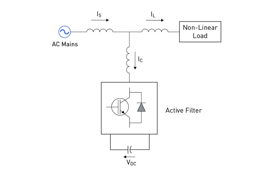
| Feature | PFC Capacitors | Active Harmonic Filters (AHF) | Static VAR Compensators (SVC) |
|---|---|---|---|
| Technology | Passive, fixed capacitance | Active, real-time harmonic mitigation | Combination of capacitors and reactors with thyristor control |
| Cost | Low to Moderate | High | Moderate to High |
| Harmonic Mitigation | Limited. Can worsen harmonic resonance if not properly sized. | Excellent. Actively reduces harmonics. | Moderate. Can provide harmonic filtering. |
| Response Time | Instantaneous. Fixed correction. | Very Fast. Real-time correction | Fast. Stepped or continuous control. |
| Complexity | Simple and Robust | Complex and Requires Advanced Control | Moderate Complexity. |
| Typical Applications | General power factor correction for various loads. | Industrial facilities with significant harmonic distortion. | Large industrial applications and grid support. |
| Limitations | Fixed reactive compensation, can cause overcorrection if load varies. | Higher cost and complexity. | Requires regular maintenance. |
The selection of a specific PFC method is highly dependent on the specific application's requirements, including load characteristics, presence of harmonics, budget constraints, and the desired level of correction. For basic power factor issues with relatively stable loads, capacitors offer a simple and affordable solution, particularly in environments where harmonic distortion isn't a major concern. However, in scenarios with significant harmonic content or fluctuating loads, AHF systems or SVCs provide more effective and adaptable performance.
Frequently Asked Questions About PFC Capacitors
This section addresses common queries regarding PFC capacitors, drawing from user questions and related searches to provide clear and concise answers. We aim to clarify their function, application, and selection to ensure optimal power factor correction.
- What is the primary function of a PFC capacitor?
The primary function of a PFC capacitor is to improve the power factor of an electrical system. It achieves this by supplying reactive power to offset the inductive reactive power drawn by loads, thereby reducing the overall apparent power and increasing the efficiency of power usage. - Where is the optimal location for a power factor correction capacitor?
Ideally, PFC capacitors should be installed as close as possible to the inductive loads they are correcting. This reduces the current flow through the distribution system, minimizing losses and improving voltage regulation. Common locations include at the motor control center (MCC), at individual motors, or at the main distribution panel. - What are common applications for PFC capacitors?
PFC capacitors are extensively used in various applications, including industrial facilities with heavy machinery, commercial buildings with HVAC systems, and even in some domestic applications with high inductive loads. Their primary use is to improve power factor and reduce energy consumption, ultimately leading to lower electricity bills and reduced wear on electrical infrastructure. - How does a power correction capacitor work?
Power correction capacitors work by storing electrical energy and releasing it back into the circuit when the voltage is lagging behind the current, which is commonly the case with inductive loads. This reactive power supplied by the capacitor counteracts the reactive power demanded by the inductive load, reducing the overall reactive power requirement from the power grid. This results in a more efficient energy transfer. - How do I calculate the appropriate size of a PFC capacitor?
Calculating the correct capacitor size requires considering the system’s reactive power requirements and the desired power factor correction level. A PFC capacitor calculator (available online) or a consult with a qualified electrical engineer can facilitate this. Typically, the calculation involves analyzing the existing power factor, the active power demand, and the desired power factor. - What is the basic formula for power factor correction using capacitors?
The basic formula to calculate the required capacitive reactive power (Qc) is based on the existing power factor (PF1) and the target power factor (PF2), along with the active power (P). The formula typically involves trigonometric functions and provides the necessary kVAr value to achieve the desired correction: Qc = P * (tan(arccos(PF1)) - tan(arccos(PF2))). This value can then be used to determine the needed capacitor size. - Where can I find the price of a PFC capacitor and what affects it?
The price of a PFC capacitor varies based on its voltage rating, capacitance (measured in Farads or microfarads), construction type, and manufacturer. Costs can also be influenced by the quantity ordered. Typically, higher voltage and capacitance ratings result in higher price, due to the increased materials and complex engineering involved in their design.
PFC capacitors are not just components; they are crucial cogs in the machine of energy efficiency. Understanding their role, benefits, and maintenance is essential for reducing energy waste and lowering operating costs. Whether you're a homeowner looking to save on your electricity bill or an industry professional optimizing complex systems, the effective use of a PFC capacitor represents a significant step towards a more sustainable and cost-effective future. By adopting the right practices and maintenance, we can harness the full potential of PFC capacitors in a world that increasingly demands efficiency and smart energy use.