Unlocking the Potential of the BT136 Triac: A Comprehensive Guide

From dimming your home lights to controlling the speed of your kitchen appliances, many electronic devices rely on a component called a triac, and the BT136 is a popular choice for efficient AC switching. This article delves into the world of the BT136 triac, exploring its functionality, specifications, and diverse applications, making complex power control understandable for everyone.
Understanding the BT136 Triac: An Overview
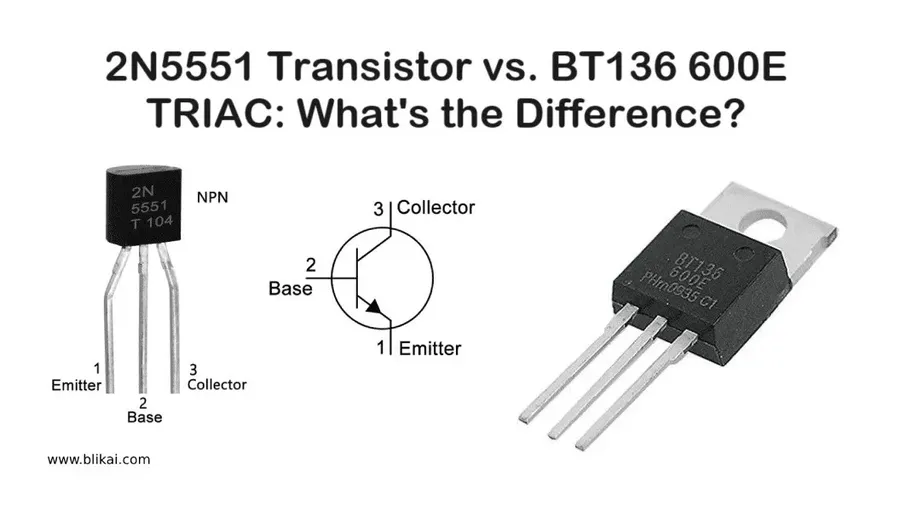
The BT136 triac is a three-terminal semiconductor device engineered for bidirectional AC power control. Functioning as a sensitive gate triac, it acts as a solid-state switch for alternating current circuits, enabling current flow in both directions upon proper gate triggering. This characteristic makes the BT136 ideally suited for various AC power control applications.
BT136 Triac Pinout Configuration
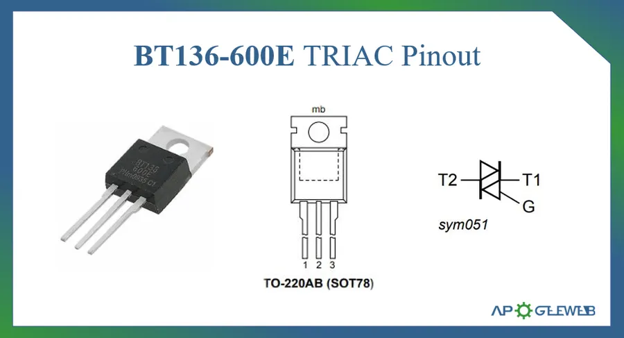
The BT136 triac is a three-terminal semiconductor device, and understanding its pin configuration is crucial for effective circuit integration. These pins are Main Terminal 1 (MT1), Main Terminal 2 (MT2), and the Gate (G). Each pin serves a specific function in controlling the flow of alternating current through the triac.
- Main Terminal 1 (MT1)
MT1 serves as one of the two terminals through which the main AC current flows. It's often considered the reference terminal in circuit designs involving the BT136. - Main Terminal 2 (MT2)
MT2 is the second terminal for the main AC current path. The direction of current flow between MT1 and MT2 is determined by the applied gate signal and the polarity of the applied voltage. - Gate (G)
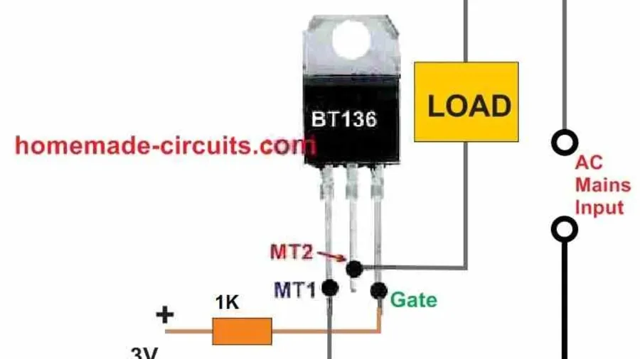
The Gate pin is the control input for the triac. A small current pulse applied to the gate can trigger the triac to switch ON and allow current flow between MT1 and MT2. The gate only needs a pulse to initiate conduction; it does not need continuous current.
The diagram below illustrates the pinout for the BT136 triac. It's important to note that MT1 and MT2 are interchangeable regarding their function in the AC current path, and the gate controls the conduction between these terminals. Proper pin identification is essential to avoid damaging the device or causing malfunction. When viewing the device with the text facing you, from left to right, the pins are typically Gate, MT2, and MT1.
Key Specifications of the BT136 Triac
Understanding the BT136 Triac's specifications is crucial for effective circuit design. These parameters dictate the triac's performance, limitations, and suitability for specific applications. Key specifications include maximum on-state current, off-state voltage, gate trigger voltage, and holding current. Each parameter plays a vital role in ensuring the triac operates safely and reliably within a given circuit.
| Parameter | BT136-600D | BT136-600E | Unit |
|---|---|---|---|
| Maximum On-State Current (IT(RMS)) | 4 | 4 | A |
| Peak Non-Repetitive Surge Current (ITSM) | 25 | 25 | A |
| Off-State Voltage (VDRM/VRRM) | 600 | 600 | V |
| Gate Trigger Voltage (VGT) | 1.3 | 1.3 | V |
| Gate Trigger Current (IGT) | 5-25 | 5-25 | mA |
| Holding Current (IH) | 10 | 10 | mA |
| Operating Junction Temperature (Tj) | -40 to 125 | -40 to 125 | °C |
The table above presents a comparison of key parameters between the BT136-600D and BT136-600E variants. The core specifications are identical, indicating that both variants offer the same fundamental operational capabilities. However, it's crucial to consult the specific datasheet for any particular variant being used, as there can be differences in parameters. The maximum on-state current of 4A determines the continuous current the triac can safely handle, while the 600V off-state voltage rating is the maximum voltage that the triac can block in its non-conducting state. The gate trigger voltage (VGT) and current (IGT), determine the voltage and current required at the gate terminal to initiate the switching of the triac from blocking to conducting state. The holding current (IH) is the minimum current that must flow through the triac to maintain conduction once it has been triggered. Finally, the Operating junction temperature (Tj) represents the maximum range of temperature for safe operation. These parameters are critical when selecting the right component for an application.
How the BT136 Triac Works: The Switching Mechanism
The BT136 triac functions as a bidirectional AC switch, allowing current flow in either direction when triggered. Its operation centers on the application of a gate trigger pulse, which transitions the device from a non-conducting (off-state) to a conducting (on-state) condition. This unique characteristic makes it ideal for AC power control applications.
Understanding the triac's internal structure is crucial to grasping its switching action. The triac has three terminals: Main Terminal 1 (MT1), Main Terminal 2 (MT2), and the Gate. When a sufficient gate current pulse is applied between the gate and MT1, the triac 'turns on,' effectively creating a low-resistance pathway between MT1 and MT2. Once triggered, the triac will continue to conduct current as long as the current through the triac exceeds its holding current threshold. The triac will turn off when the current through the triac drops below the holding current. Because the triac is a bidirectional switch, the gate trigger pulse can be either positive or negative with respect to MT1, allowing it to control AC current efficiently.
The behavior of the BT136 can be illustrated through a simplified operational model:
- Off-State
With no gate current applied, the triac is in a high-resistance state, blocking current flow between MT1 and MT2. The device operates as an open circuit and no AC power is delivered to the load. - Triggering
When a gate current is applied between gate and MT1, the triac enters a low-resistance on-state. The voltage between MT1 and MT2 breaks down, initiating current flow from MT2 to MT1 or from MT1 to MT2, depending on the instantaneous polarity of the AC supply. The gate pulse does not need to be constantly applied. Instead, the triac will remain on as long as the current through the device is greater than its holding current, making it suitable for applications such as AC dimming. - On-State
The triac continues to conduct as long as the current through MT1 and MT2 is above the holding current value. The device now behaves like a closed switch, allowing the flow of current in both directions across the main terminals. - Turning off
When the AC supply voltage reverses or the current falls below the holding current, the triac will naturally revert to its off state, thereby blocking any flow of current and acting as an open circuit again until the next trigger pulse.
The switching behavior of the BT136 triac is highly versatile and has a large range of applications, offering a simple and efficient mechanism for AC power control. Its ability to control both halves of an AC waveform is paramount in achieving smooth power regulation in applications like motor speed control and light dimmers.
BT136 Triac Applications: Where Is It Used?
The BT136 triac stands out as a versatile and cost-effective solution for AC power control across various applications. Its ability to switch alternating current bidirectionally makes it ideal for scenarios requiring efficient, compact, and economical power regulation. This section will delve into specific examples showcasing the practical implementation of the BT136.
The BT136 shines in applications requiring precise control of AC power, demonstrating its versatility in both residential and industrial environments. Its bi-directional switching capability, coupled with cost-effectiveness and compact design, positions it as a preferred choice for AC control solutions.
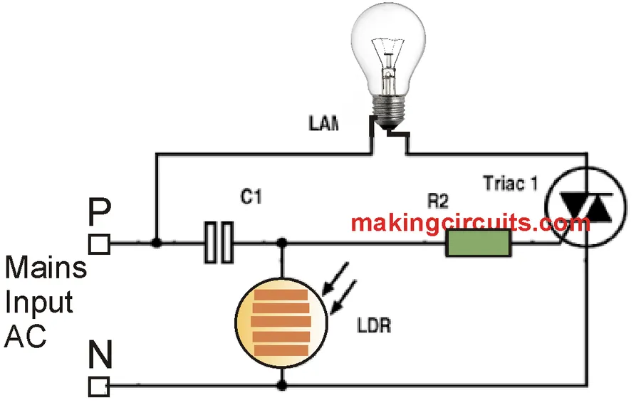
- Light Dimmers
BT136 triacs are fundamental components in light dimmers, enabling smooth and gradual adjustment of lighting intensity. By controlling the phase angle of the AC waveform, the triac effectively regulates the power delivered to the lamp, allowing for seamless dimming effects. The use of the BT136 offers precise dimming control, is compact in size and cost effective when compared to other solutions. This is why it is widely used in domestic lighting circuits. - Motor Speed Controllers
In motor speed control applications, the BT136 regulates the AC power supplied to motors, thereby controlling their speed. This is especially useful in household appliances like fans and small power tools, where variable speed control enhances functionality and efficiency. This offers a simple and reliable solution to speed control applications. - AC Power Switches
The BT136 acts as an efficient AC power switch in various scenarios, from simple on/off controls to more complex automated systems. It handles AC current effectively, offering a robust solution for switching power in devices and appliances, which is why it is widely adopted in numerous applications. - Home Automation Systems
The compactness and cost-effectiveness of the BT136 make it an attractive component for home automation systems. It controls various household devices such as lighting and small appliances, which contribute to automated living spaces that are both efficient and easy to manage. These systems often utilize the BT136 to implement smart home solutions, including energy management and remote control capabilities.
Each of these applications highlights the BT136's ability to provide an efficient, compact, and inexpensive power control solution. By utilizing the BT136, designers can create compact, cost-effective solutions for AC power management that require precision and reliability.
Selecting the Right Triac: BT136 vs. Alternatives
Choosing the appropriate triac for a specific application is crucial for optimal circuit performance and reliability. While the BT136 is a versatile option for many AC control tasks, understanding its limitations and comparing it to alternatives like the BTA16 is essential for making informed design decisions. This section outlines the scenarios where BT136 excels and when other options might be more suitable.
| Feature | BT136 | BTA16 |
|---|---|---|
| Maximum On-State Current (IT(RMS)) | 4A | 16A |
| Maximum Off-State Voltage (VDRM) | 600V | 600V-800V |
| Gate Trigger Current (IGT) | Typically 5-25mA | Typically 25-50mA |
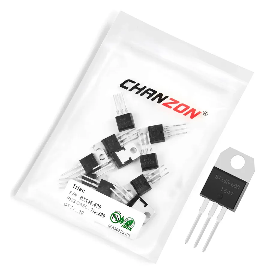
| Package | TO-220 | TO-220 |
| Typical Applications | Light dimmers, small motor control, basic AC switching | Higher power motor control, heating elements, industrial power control |
| Cost | Lower | Higher |
| Advantages | Lower gate trigger current, more sensitive, cost-effective for lower power applications | Handles higher current, more robust in high-power situations, larger heat dissipation capacity |
| Disadvantages | Limited current handling, may require additional heat sinking at higher currents | Higher gate trigger current, less sensitive gate requiring more gate current to trigger |
When to choose the BT136: The BT136 is ideal for applications that require relatively low current control, such as light dimmers, small appliance motor speed controllers, or basic AC switches. Its low gate trigger current makes it easy to interface with microcontrollers and logic circuits. Its lower cost also makes it an attractive option for cost-sensitive applications where 4A is sufficient. Alternative Options: For higher current applications, the BTA16 or similar higher rated triacs are preferred. The BTA16, for example, can handle up to 16A. Other alternatives include triacs with different voltage ratings depending on your mains supply and other specific requirements. Consider also the specific package for the project where a through-hole package might not be best for dense PCBs.
Designing with the BT136: Practical Considerations
Successful implementation of the BT136 triac hinges on careful design and adherence to established best practices. This section details crucial aspects like gate trigger circuit design, thermal management, voltage rating considerations, and common pitfalls to avoid, ensuring robust and reliable performance.
Here's a summary of key design considerations:
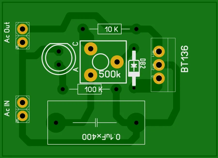
- Gate Trigger Circuitry
The gate trigger circuit provides the necessary current to switch the triac from its off-state to its on-state. It is essential to select a trigger circuit capable of delivering the required gate current (I_GT) specified in the datasheet. Typical trigger circuits may include resistors, capacitors, and other semiconductor components. - Heat Sinking
Triacs, like other power semiconductor devices, generate heat during operation. A heat sink is generally required for the BT136 to dissipate excess heat, preventing thermal damage and performance degradation. The size and material of the heat sink depend on the operating current and ambient temperature. Consider the maximum junction temperature (Tj max) from the datasheet. - Voltage Rating
Ensuring that the selected BT136 variant has a voltage rating (VDRM, VRRM) that exceeds the maximum expected voltage in the application. Exceeding the voltage limits leads to triac failure, potentially damaging other parts of the circuit. - Snubber Circuits
A snubber circuit, typically consisting of a series RC network, is often connected across the main terminals of the triac to suppress voltage transients. Transients can cause false triggering or damage, a snubber can help mitigate these effects, particularly when inductive loads are involved. - Common Design Mistakes
Common mistakes include failing to provide proper heat sinking, using an inadequate gate drive circuit, selecting a device with insufficient voltage rating, and ignoring transient protection. Thoroughly reviewing the device's datasheet, and incorporating proper design practices mitigates most common errors.
Below is a basic example showing how to use a microcontroller to control the BT136 triac gate. It should be noted that while the following example is simplified, in a real-world implementation there are isolation techniques and protection mechanisms that should be considered, this is for instructional purposes.
/* Pseudo-code for microcontroller control of a BT136 triac gate */

void setup() {
  pinMode(gatePin, OUTPUT); // Define the gate pin as an output
}

void loop() {
  // Control the gate by sending a pulse to activate triac
  digitalWrite(gatePin, HIGH); // Send a trigger pulse
  delayMicroseconds(triggerPulseWidth); // Width of the gate trigger pulse
  digitalWrite(gatePin, LOW);  // Turn off the gate
  delay(delayTime);           // Time between on cycles
}
Frequently Asked Questions about the BT136 Triac
This section addresses common questions regarding the BT136 triac, providing clear, concise answers to enhance understanding and facilitate effective application of this versatile semiconductor device. The questions cover its uses, alternatives, specific applications, and advantages over other switching methods, drawing from both user queries and engineering principles.
- What is the primary function of a BT136 triac?
The BT136 triac functions as a bidirectional AC switch. It controls the flow of alternating current in both directions, making it suitable for applications where current direction changes, such as light dimmers and motor speed controllers. Its core role is to act as a solid-state switch for AC power. - What are some common equivalent components to the BT136 triac?
While the BT136 is a popular choice, equivalent components include other triacs with similar voltage and current ratings. Specifically, the BTA series, such as the BTA16, is a common alternative for higher current applications. The selection of an equivalent depends on the specific requirements of the circuit, considering factors like current capacity and voltage ratings. - In what specific applications is the BT136 Triac commonly used?
The BT136 is frequently used in light dimmers, motor speed controllers for small AC motors, and as a solid-state AC switch in various home automation systems. Its compact size and efficiency make it a popular component in low-to-medium power AC control circuits. - Why should a triac like the BT136 be chosen over other switching methods?
Triacs offer the advantage of bidirectional current control with a single component, which simplifies circuit design for AC applications. Other switching methods, such as relays, are mechanical and tend to have a shorter lifespan. A triac offers silent, solid-state switching, with fast response times, and higher reliability, making it more suited to applications where frequent switching is required and where mechanical noise is undesirable. - What are the key differences between a BT136-600D and a BT136-600E?
The key difference between the BT136-600D and BT136-600E variants typically lies in their gate trigger sensitivity and packaging. While both have similar maximum voltage and current ratings, the -600E might have slightly higher gate trigger sensitivity. For precise specifications, consulting the specific datasheet for each variant is crucial. - What considerations are important for heatsinking a BT136?
Heatsinking for the BT136 becomes critical when it operates at or near its maximum current ratings. Proper heatsinking ensures that the device's junction temperature stays within acceptable limits, preventing thermal damage and ensuring long-term reliability. The required heatsink size is determined by the power dissipation of the triac, which depends on the current flowing through it and the voltage drop across it while in operation. Failure to provide sufficient heatsinking can lead to overheating and premature failure of the triac. - What are the common pitfalls to avoid when designing with a BT136?
Common pitfalls include exceeding the device's current or voltage ratings, inadequate gate drive, and insufficient heat sinking. Another key pitfall is not understanding that a triac may switch off at low load currents. A snubber network is frequently required to mitigate any inductive current and also to prevent unintended turn on from rate of change of voltage, also known as dv/dt immunity. Following design guidelines, referring to the device's datasheet, and thorough testing are crucial to avoid these mistakes.
Where to Buy BT136 Triacs and Considerations for Purchase
Purchasing BT136 triacs requires careful consideration of supplier reputation, component authenticity, and quality. This section aims to guide users in making informed purchasing decisions, ensuring they acquire reliable components for their projects. Selecting a trustworthy source is crucial to avoid counterfeit parts and ensure the triacs meet specified performance characteristics.
- Trusted Suppliers
Opt for established electronic component distributors known for their quality control and customer service. Major distributors often provide datasheets and traceability, ensuring product legitimacy. Consider suppliers like Mouser Electronics, Digi-Key Electronics, Arrow Electronics, and Farnell. These distributors have robust supply chains and work directly with manufacturers or authorized dealers. - Verify Component Authenticity
Counterfeit electronic components pose significant risks. Inspect the packaging for any signs of tampering or poor printing. Check the markings on the triac itself against the datasheet specifications and manufacturer's logo. Reputable distributors provide certificates of conformity, which confirms the components meet the required standards. - Bulk vs. Single Purchases
If you are prototyping or conducting small projects, buying single pieces from reputable suppliers is sufficient. However, for larger scale production, purchasing in bulk may result in cost savings. Check supplier websites to see if they offer price reductions for larger volumes. - Datasheet Verification
Before purchasing, cross-reference the supplier's part number with the manufacturer's datasheet. Compare specifications, particularly the voltage and current ratings, to ensure the BT136 variant matches your application requirements. Be aware of any potential differences among the BT136-600D and BT136-600E, or other variations. - Checking for Quality
Examine the triacs physically, checking for any cracks, bent leads, or signs of previous use or damage. If purchasing online, check feedback from past customers. If possible, perform a preliminary test to confirm they operate correctly according to the datasheet specifications. If the part is not performing up to spec, you may need to return it. - Component Storage
If you are buying in bulk, consider your storage needs. Electronic parts need to be kept at room temperature away from humidity, direct sunlight, and static electricity. Consider anti-static bags or trays to keep the parts safely stored. - Price Comparison
Compare prices from different suppliers, keeping in mind the points above. Price should not be the sole criteria as authenticity and quality are crucial. If a deal seems too good to be true, it probably is. Be mindful that counterfeit parts are a growing problem and that they are often sold at very attractive prices.
The BT136 triac is a cornerstone of modern AC power control, offering a robust and versatile solution for a variety of electronic applications. From home automation to industrial motor control, its ability to efficiently switch AC power makes it indispensable. Understanding its nuances, from its pinout to its applications, empowers engineers and hobbyists to harness its full potential. With this information, you are well-equipped to confidently integrate the BT136 triac into your next project, ensuring reliable and efficient power management.