Unlocking the Power of Dynamic Brake Resistors: A Comprehensive Guide
Imagine a high-speed train smoothly slowing down, converting its kinetic energy into manageable heat. Similarly, in industrial motor control, dynamic brake resistors act as vital components, efficiently dissipating the excess energy produced during braking by AC variable frequency drives (VFD). This article delves into the inner workings, applications, and selection criteria of dynamic brake resistors, bridging the gap between theoretical knowledge and practical use.
What is a Dynamic Brake Resistor and How Does it Work?
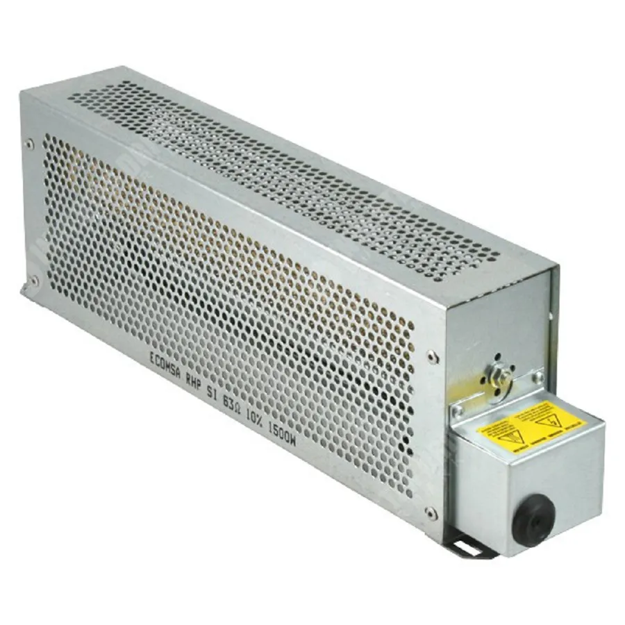
A dynamic brake resistor (DBR) is a crucial component in variable frequency drive (VFD) systems, designed to safely dissipate excess energy generated during motor deceleration. When a motor is driven by a VFD, the motor can sometimes act as a generator, particularly during rapid deceleration or when the load is overhauling (driving the motor). This generates electrical energy that needs to be managed to prevent overvoltage in the drive. The DBR provides a path for this excess energy to be converted into heat, thus enabling controlled braking.
The fundamental principle behind a DBR's operation is the conversion of kinetic energy into thermal energy through electrical resistance. During braking, the VFD redirects the generated energy from the motor to the DBR. The resistor's material and design cause electrical current to flow through the resistive element, resulting in the generation of heat. This heat is then dissipated into the surrounding environment. This process effectively slows down the motor by converting its kinetic energy into non-recoverable heat, ensuring a controlled stop and preventing damage from overvoltage in the VFD's intermediate DC bus.
The Crucial Role of Dynamic Brake Resistors in VFD Systems
Dynamic brake resistors (DBRs) are indispensable components in Variable Frequency Drive (VFD) systems, enabling efficient and controlled braking of motors. In VFD-controlled motor applications, the inherent nature of decelerating loads results in the motor acting as a generator, feeding energy back into the DC bus of the VFD. This regenerative energy, if not managed, can cause overvoltage conditions, which in turn can damage the VFD, lead to system instability, and increase system downtime. DBRs provide a path for this excess energy to be safely dissipated, typically as heat, allowing for smooth and safe deceleration of the motor.
The integration of DBRs within VFD systems is fundamental to ensure the overall system stability and prevent damage resulting from regenerative braking. By effectively managing excess energy, DBRs enable VFDs to achieve optimal performance, thus ensuring precise motor control, preventing overvoltage trips, and improving overall operational safety and reliability.
- Efficient Braking
DBRs facilitate rapid and controlled motor deceleration, which is crucial for applications that require precise stopping. - Overvoltage Prevention
By dissipating excess energy, DBRs protect the VFD from harmful overvoltage conditions, thus preventing damage and ensuring the VFD's stable operation. - System Stability
The use of DBRs contributes to the stability of the entire system by preventing the accumulation of regenerative energy. - Improved Motor Performance
Effective braking control provided by DBRs enhances the performance and longevity of the motor.
Understanding Regenerative Braking and Dynamic Braking
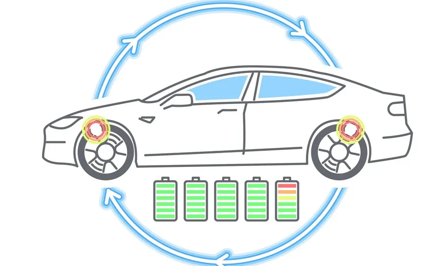
Regenerative braking and dynamic braking are both methods used to decelerate a motor, but they differ significantly in how they manage the kinetic energy. Regenerative braking attempts to capture the kinetic energy and return it to the power supply, while dynamic braking dissipates this energy as heat. Understanding their differences is crucial for selecting the appropriate braking method for a given application.
| Feature | Regenerative Braking | Dynamic Braking |
|---|---|---|
| Energy Handling | Converts kinetic energy back into electrical energy, feeding it back into the power supply. | Converts kinetic energy into heat, which is dissipated through a resistor. |
| Efficiency | Potentially more energy-efficient, as it recovers energy. | Less energy-efficient, as it wastes energy as heat. |
| Hardware | Requires specialized inverters and power management systems capable of handling regenerative current. | Requires a braking resistor and a switching mechanism to connect the resistor to the drive. |
| Complexity | More complex control algorithms are required. | Simpler implementation and control. |
| Suitability | Ideal for applications where energy can be effectively reused and the power grid can accept the return power. | Suitable for applications where regenerative energy is too high to be practically managed or the power grid is not suitable to accept the feedback. |
| Cost | Higher initial cost due to specialized equipment and control. | Lower cost as it uses readily available components. |
| Application | Common in electric vehicles, elevators, and some industrial applications. | Common in VFD systems where controlled deceleration is needed. |
In essence, regenerative braking is a form of energy recovery, while dynamic braking is a form of energy dissipation. The choice between them depends on the application's specific requirements for efficiency, energy management, and cost.
Dynamic Brake Resistor Applications

Dynamic brake resistors (DBRs) are indispensable components in various industrial and commercial applications where precise control over deceleration and high dynamic performance are critical. These applications typically involve machinery with significant inertial loads or frequent stop-start cycles, where the kinetic energy generated during braking needs to be safely dissipated. The efficient functioning of DBRs ensures that motors can decelerate rapidly without causing damage to the drive system or other components.
Here are some key areas where DBRs are essential:
- Cranes and Hoists
In lifting applications, DBRs are used to control the descent of heavy loads. Without them, the regenerative energy can lead to overvoltage issues within the VFD and uncontrolled, unsafe lowering speeds. Dynamic braking provides a consistent and controlled way of slowing down, ensuring safety and reliability. - Elevators and Escalators
Elevators require precise speed control during starts, stops, and constant motion. DBRs ensure smooth deceleration, preventing abrupt stops that could endanger passengers. This is especially important during downward movement where gravity assists the motor, requiring significant braking power. - Conveyors
Conveyor systems often involve large inertial loads, and precise control of deceleration is critical to prevent material spills and ensure smooth operation. DBRs enable conveyors to stop efficiently, improving system reliability. - Wind Turbines
Wind turbines utilize DBRs to provide braking during high winds, preventing damage to the blades and gearbox. This is essential to ensure the long-term reliability and safety of the turbine. - Automated Guided Vehicles (AGVs)
AGVs require smooth and consistent braking for precise navigation and safe operation within automated facilities. DBRs allow these vehicles to decelerate as needed while maintaining stability. - Test Benches
Motor test benches often require DBRs to effectively absorb excess energy during various testing cycles, ensuring consistent and reliable results during motor evaluations. - Printing and Packaging Machines
These machines use DBRs for precise control of motion and speed during start and stop phases, ensuring accurate and repeatable processes, reducing material waste and improving production efficiency.
Selecting the Right Dynamic Brake Resistor: Key Factors to Consider
Choosing the appropriate dynamic brake resistor (DBR) is crucial for the efficient and safe operation of variable frequency drive (VFD) systems. The selection process involves careful consideration of various parameters to ensure the resistor can effectively dissipate the regenerative energy produced during motor deceleration, preventing overvoltage and maintaining system stability.
Here are the critical factors to evaluate when selecting a dynamic brake resistor:
- Power Rating
The resistor's power rating must be sufficient to handle the energy it needs to dissipate. It is measured in watts and indicates the amount of heat the resistor can continuously handle without damage. The power rating should match or exceed the peak regenerative power produced by the drive during braking. - Resistance Value
The resistance value, measured in ohms, is critical in determining the braking torque. A lower resistance value provides stronger braking but requires a higher current, while a higher resistance value results in a weaker braking force with lower current. It should be chosen to achieve optimal braking performance while avoiding overcurrent. - Duty Cycle
The duty cycle specifies how often the resistor is used for braking. It is typically expressed as a percentage. High duty cycles require resistors with higher thermal capacity or heat dissipation capabilities. For continuous braking applications, a robust resistor with adequate thermal characteristics is essential. - Operating Voltage
The resistor's operating voltage must match or exceed the DC bus voltage of the VFD system. Selecting a resistor with a lower voltage rating will lead to premature failure, whereas excessively high voltage ratings can be less cost-effective. Ensuring voltage compatibility is paramount. - Peak Regenerative Power
This parameter is the maximum power generated by the motor during the most demanding braking operation. The resistor must handle this power without overheating or damage. Manufacturers typically provide data on the drive's peak regenerative power, aiding in proper resistor selection. - Ambient Temperature
The ambient temperature affects the resistor's ability to dissipate heat. High ambient temperatures reduce the resistor's thermal capacity, so this must be accounted for. Derating the resistor's power rating may be necessary in high-temperature environments to prevent overheating and ensure longevity.
These considerations require careful calculations and analysis to ensure the DBR can withstand the braking requirements of the specific application. It may be necessary to consult engineering guidelines or seek guidance from a qualified VFD system engineer to guarantee the appropriate resistor is selected for the optimal and safest performance.
Dynamic Brake Resistor Connection and Installation
Proper connection and installation of a dynamic brake resistor (DBR) within a Variable Frequency Drive (VFD) system are critical for ensuring safe and efficient operation. This section provides a step-by-step guide, emphasizing safety protocols and precise wiring procedures to prevent damage and optimize braking performance.
- Step 1: Safety First - Power Isolation
Before commencing any installation work, ensure that the VFD is completely powered down and isolated from the main power supply. Verify this using appropriate voltage testing equipment. Lockout/Tagout (LOTO) procedures must be strictly followed to prevent accidental energization during the connection process. - Step 2: Verify Resistor Specifications
Confirm that the selected dynamic brake resistor matches the VFD's specifications, including the resistance value (Ohms), power rating (Watts), and operating voltage. Incompatible specifications can lead to component damage and inefficient braking. Refer to the VFD manufacturer's manual for detailed requirements. - Step 3: Locate the Braking Terminals
Identify the dedicated braking terminals on the VFD. These are typically labeled as 'B1' and 'B2' or 'DC+' and 'DC-'. Consult the VFD manual to locate the braking terminals specific to the equipment. These terminals are usually separate from the main power terminals. - Step 4: Wire the Resistor to the VFD
Using the appropriately sized and rated wiring, connect one terminal of the braking resistor to the designated ‘B1’ or ‘DC+’ terminal on the VFD. Connect the other terminal of the braking resistor to the ‘B2’ or ‘DC-’ terminal. Ensure that the connections are tight and secure. For higher power applications, additional care should be taken to use proper lugs and torque on terminal screws. - Step 5: Verify Wiring Connections
Double check all wiring connections for accuracy. Verify that there are no loose strands or improper wiring. A poorly connected DBR can cause unreliable braking, overheating, or damage to the VFD. Make certain all terminals screws have been tightened to the manufacturer's specifications. - Step 6: Secure the Resistor
Mount the DBR securely to a suitable location that allows for adequate airflow and heat dissipation. Consider using standoff hardware to maintain a sufficient air gap between the resistor and the mounting surface. Avoid placing the resistor near flammable materials and consider the ambient temperature of the environment to ensure the resistor can operate within its rated limits. Ensure the mounting location is vibration free and securely fastened. - Step 7: Initial Power-Up and Verification
After installation, gradually apply power to the VFD and monitor the braking function. Observe for any abnormal heating of the resistor, unusual noises from the VFD, or error messages. If any issues are observed, shut down the system immediately and check the installation and connections. Use monitoring equipment to verify that the brake function is as designed.
Frequently Asked Questions About Dynamic Brake Resistors
This section addresses common inquiries regarding dynamic brake resistors (DBRs), providing concise and authoritative answers to enhance understanding of their functionality and applications in variable frequency drive (VFD) systems.
- What exactly is a dynamic brake resistor?
A dynamic brake resistor is a component used in variable frequency drive (VFD) systems to dissipate excess energy generated during motor deceleration. It converts the kinetic energy of the rotating motor into heat, which is then safely released into the surrounding environment. This prevents overvoltage conditions in the VFD and allows for controlled braking. - What is the primary function of a dynamic braking resistor?
The primary function of a braking resistor is to provide a controlled path for excess regenerative energy produced by the motor during deceleration or overhauling conditions. By converting this energy into heat, it prevents the energy from feeding back into the VFD's DC bus, thus preventing overvoltage faults and ensuring safe and efficient braking. - What is the 'work' of a DBR in the context of a VFD system?
The 'work' of a DBR is to act as a load for the energy generated by a motor during braking. When the motor slows down, it acts as a generator, and the braking resistor provides a pathway for this energy to be consumed. This process is crucial for maintaining system stability and preventing damage to the VFD. - How does dynamic braking function within a motor control system?
Dynamic braking works by converting a motor's rotational kinetic energy into electrical energy and then dissipating it as heat through the resistor. During deceleration, the motor acts as a generator, feeding power back into the VFD. The DBR provides a load to absorb this power, creating a braking torque on the motor shaft. - What is the underlying principle of operation for a dynamic braking resistor?
The fundamental principle is based on Ohm's law and Joule's law. The resistor, when connected to the VFD, provides a load that converts the electrical energy back into heat. This conversion is directly proportional to the current and the resistance value. The heat is then dissipated into the environment. This ensures controlled energy dissipation, preventing voltage spikes on the DC bus. - Why are braking resistors necessary in variable frequency drive (VFD) applications?
Braking resistors are necessary in VFD applications to prevent overvoltage situations that can occur during rapid motor deceleration or when the driven load has a high inertia. Without a braking resistor, the regenerative energy from the motor can quickly elevate the DC bus voltage of the VFD, leading to component damage or system shutdown. Using a DBR maintains the drive within safe operating limits. - Where can I find braking resistor calculation information and PDFs for VFDs?
Braking resistor calculations involve determining the appropriate resistance and power rating based on the motor's characteristics, braking torque needed, duty cycle, and VFD specifications. These calculations are typically detailed in the VFD's manual and manufacturer resources. Additional information, such as application notes and sample calculations, can often be found on VFD manufacturer's websites and various industry publications or by searching academic databases. PDF documents for specific VFDs can be found on the VFD manufacturer's website. Proper sizing is critical to efficient operation and avoiding overheating.
Troubleshooting Common Issues with Dynamic Brake Resistors
Dynamic brake resistors, while robust, can encounter operational issues. Identifying and addressing these problems promptly is crucial for maintaining the efficiency and safety of VFD systems. Common issues include overheating, performance degradation, and outright failure. Effective troubleshooting involves a systematic approach to pinpoint the root cause and apply corrective actions.
- Overheating
Overheating is a frequent concern, typically stemming from excessive power dissipation or inadequate cooling. This can be caused by either a too low value resistor, or too frequent or long duration braking. Check the resistor's specifications against the application requirements. Ensure proper heat dissipation by verifying the heat sink is clean, and the surrounding airflow is adequate. Verify the duty cycle against the original design and adjust the operation if necessary. - Performance Degradation
Performance issues can present as reduced braking torque or inconsistent deceleration. Potential causes include damaged or partially failed resistor elements, poor electrical connections, and incorrect resistor selection for the application. Check the resistance of the resistor against the design value. Confirm that the resistor is connected to the correct location, and inspect all the wiring for loose or corroded connections. - Resistor Failure
A complete failure of the resistor can result in an inability to brake, potentially leading to system damage or safety hazards. Such failures can be due to thermal runaway, mechanical damage, or electrical overstress. Inspect the resistor for physical damage such as cracks or burn marks. If the resistor is open circuit, replace with the correct type and value and adjust braking profiles if necessary. Verify that the braking power does not exceed the capability of the braking resistor. - Incorrect Resistance Value
If the resistance value is incorrect it can result in over heating, slow braking and even damage to the VFD. Check the nameplate value against the value required for the VFD and the application. Replace with the correct type and value. - Wiring issues
Incorrect wiring, loose connections or even corrosion can cause issues with the braking resistor. Check all connections, the type of wire used and clean connections if necessary.
Comparing Different Types of Dynamic Brake Resistors
Dynamic brake resistors are not monolithic; they vary significantly in construction, materials, and cooling methods, each tailored to specific applications and operational demands. Understanding these differences is crucial for optimal system performance and reliability. This section provides a comparative analysis of common types, highlighting their strengths and ideal use cases.
| Resistor Type | Construction | Material | Cooling Method | Typical Applications | Advantages | Disadvantages |
|---|---|---|---|---|---|---|
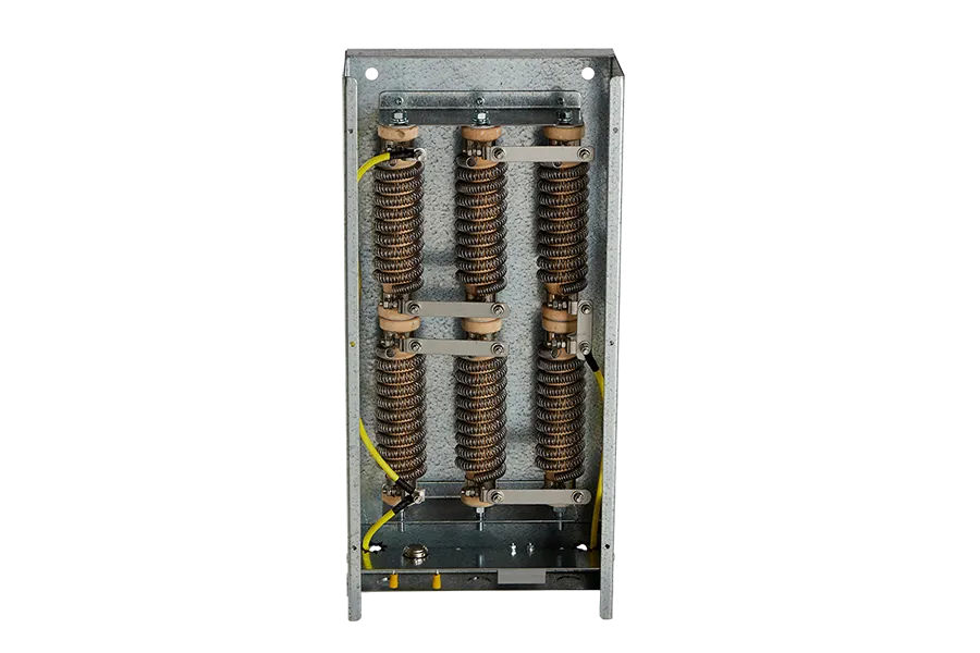
| Wire-wound Resistors | Wire coiled around a ceramic or fiberglass core. | Nickel-chromium, copper-nickel alloys. | Natural convection or forced air. | General purpose VFD applications, light industrial machinery. | Low cost, readily available, wide range of resistance values. | Can be bulky, lower power handling capabilities compared to other types, not suitable for extreme environments. |
| Edge-wound Resistors | Metal strip wound on edge around a support structure. | Stainless steel, nickel alloys. | Natural convection or forced air. | Medium power applications, traction systems, heavy machinery. | High power handling capability, robust construction, good heat dissipation. | Higher cost compared to wire-wound, can be more complex to manufacture. |
| Metal Grid Resistors | Series of interconnected metal grids or plates. | Stainless steel, iron-chromium alloys. | Forced air or liquid cooling. | High power, heavy-duty braking applications, cranes, wind turbines. | Extremely robust, very high power handling capabilities, suitable for harsh environments. | Large size, higher cost, require more complex cooling solutions. |
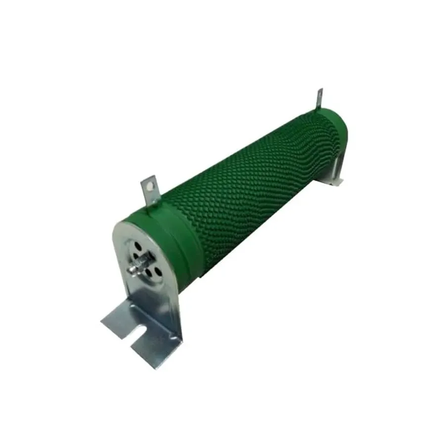
| Ceramic Encased Resistors | Resistive element embedded in a ceramic casing. | Proprietary resistive ceramic compounds. | Conduction through ceramic case to heat sink. | Compact applications with limited space, high reliability requirements. | Compact size, excellent electrical insulation, good thermal stability. | Relatively higher cost, may not be suitable for very high power dissipation. |
| Film Resistors | Thin film of resistive material deposited on a substrate. | Various metal alloys and metal oxides. | Conduction and convection. | Precision braking applications, where high accuracy is needed. | High precision, low inductance, can be made very small. | Lower power handling, typically not used in high-power applications. |
Dynamic brake resistors are vital for the safe and efficient operation of many industrial applications, facilitating precise control and energy management within VFD systems. Their ability to dissipate energy as heat allows for controlled braking, enhancing system performance, and ensuring reliable motor control. Understanding the nuances of selection, installation, and troubleshooting is crucial for optimal performance and longevity. By leveraging the appropriate dynamic brake resistor for a given application, one can ensure seamless operation and the long-term reliability of their electrical systems, contributing to the efficient management of energy in diverse industrial settings.