Unlocking the Power of Parallel Capacitors: A Comprehensive Guide
In the realm of electronics, just as athletes train to maximize their potential, engineers use capacitors in parallel to boost performance and meet specific energy storage needs. Connecting capacitors in parallel is not just a simple addition; it's a strategic approach to enhance capacitance, manage current, and improve circuit behavior. This article demystifies the concept of capacitors in parallel, providing a clear understanding of their functions, benefits, and calculations.
Understanding the Basics of Capacitors and Capacitance
Capacitors are fundamental electronic components that store electrical energy in an electric field. This ability to store charge, known as capacitance, is measured in farads (F). A capacitor's capacitance determines how much charge it can store for a given voltage, with the relationship being directly proportional; increasing voltage results in a directly proportional increase in charge stored.
The fundamental relationship defining capacitance (C) is expressed as Q = CV, where Q represents the charge stored in coulombs (C), V is the voltage across the capacitor in volts (V). This equation highlights the direct proportionality between charge storage and capacitance at a given voltage.
| Parameter | Symbol | Unit |
|---|---|---|
| Capacitance | C | Farad (F) |
| Charge | Q | Coulomb (C) |
| Voltage | V | Volt (V) |
What Does 'Capacitors in Parallel' Mean?
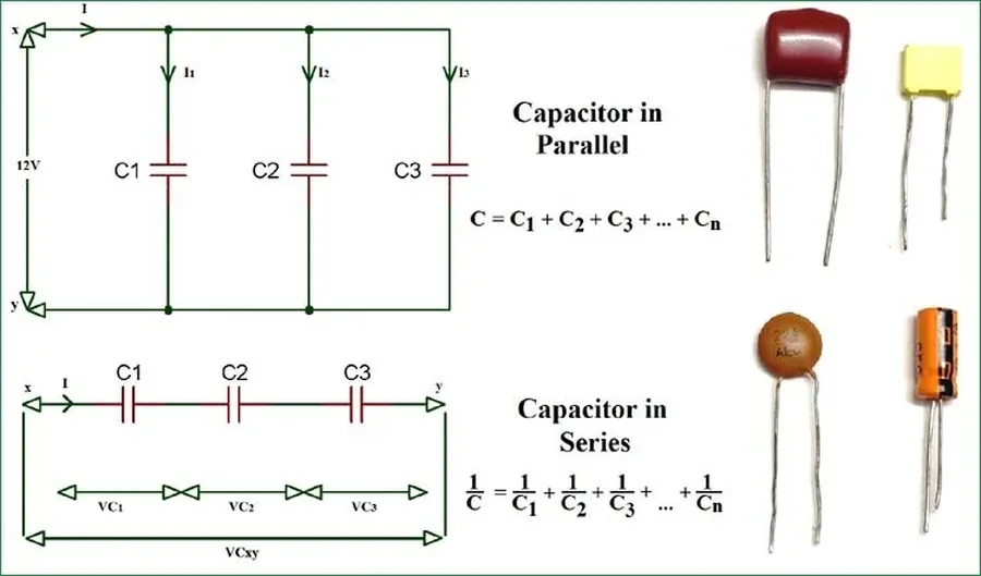
In electrical engineering, 'capacitors in parallel' refers to a specific circuit configuration where multiple capacitors are connected side-by-side, with their respective terminals directly joined. This arrangement ensures that the voltage across each capacitor is identical, as they are all connected to the same two electrical nodes. Understanding this fundamental concept is crucial for designing circuits that require specific capacitance and energy storage characteristics.
Calculating Total Capacitance of Parallel Capacitors
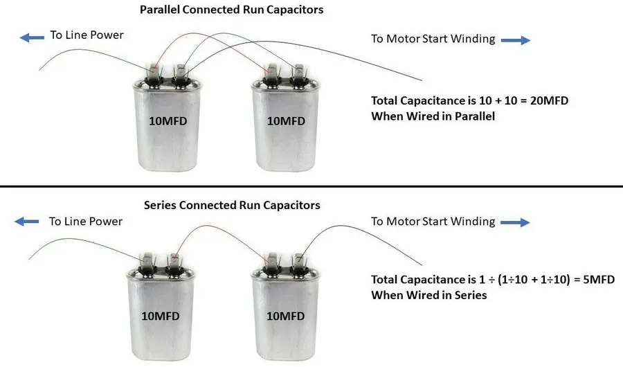
The total capacitance of capacitors connected in parallel is simply the sum of their individual capacitances. This principle arises from the fact that in a parallel configuration, the effective plate area for charge storage increases, thus enhancing the overall capacitance. This is a fundamental concept in electrical engineering, crucial for circuit design and analysis.
The formula to calculate the total capacitance (C_total) of capacitors in parallel is given by:
C_{total} = C_1 + C_2 + C_3 + ... + C_n
Where C1, C2, C3, ..., Cn represent the capacitance of each individual capacitor. This formula is valid regardless of the number of capacitors connected in parallel.
Let's illustrate this with some practical examples:
| Capacitor | Capacitance (F) | Total Capacitance (F) |
|---|---|---|
| C1=1μF, C2=2μF | 1μF, 2μF | 3μF |
| C1=10nF, C2=20nF, C3=30nF | 10nF, 20nF, 30nF | 60nF |
| C1=0.1F, C2=0.2F, C3=0.3F, C4=0.4F | 0.1F, 0.2F, 0.3F, 0.4F | 1F |
Why Use Multiple Capacitors in Parallel?
Employing multiple capacitors in parallel offers significant advantages over using a single capacitor, particularly in scenarios requiring enhanced capacitance, reduced equivalent series resistance (ESR), and the ability to handle larger currents. This configuration is a fundamental technique in electronics design that allows for performance optimization not achievable with individual components.
- Increased Total Capacitance
The primary benefit of connecting capacitors in parallel is the increase in total capacitance. The total capacitance of parallel capacitors is the sum of the individual capacitances, allowing the circuit to store more electrical charge compared to using a single capacitor. - Reduced Equivalent Series Resistance (ESR)
ESR is an important factor, especially at high frequencies, and by placing multiple capacitors in parallel, the overall ESR is reduced. This reduction allows for more efficient charging and discharging and less energy loss, resulting in more stable and robust circuits. The reduction in ESR is inversely proportional to the number of parallel capacitors. - Enhanced Current Handling Capability
Parallel capacitor configurations offer a better capacity to handle current than a single capacitor. With the current being distributed between the parallel branches of the capacitors, this will result in less heat and stress in comparison to single capacitor when high-current loads are being applied. - Effective Filtering and Decoupling
Parallel capacitor arrangements are crucial in filtering applications, smoothing voltage fluctuations and noise in power supply lines and other circuits. The reduced ESR enhances the ability to respond effectively to transient loads with low impedance.
Practical Applications of Parallel Capacitors

Parallel capacitor configurations are ubiquitous in modern electronics, serving critical roles in various applications by enhancing performance, ensuring stability, and optimizing energy management. These applications leverage the increased total capacitance, reduced equivalent series resistance (ESR), and improved current handling capabilities inherent in parallel capacitor setups.
- Power Supply Smoothing
In power supplies, capacitors in parallel are crucial for smoothing voltage fluctuations, often called ripple. This is accomplished by storing energy when the voltage is high and releasing it when the voltage dips, thus stabilizing the output and protecting sensitive electronic components. Large capacitor banks are frequently utilized to handle these large currents and stabilize the voltage for a wide variety of devices. - Decoupling in Digital Circuits
Digital circuits, especially high-speed ones, require decoupling capacitors connected in parallel and located close to integrated circuits (ICs) and microprocessors to maintain signal integrity. These capacitors provide a local charge reservoir and reduce voltage fluctuations caused by the fast switching of transistors and other electronic components. This helps to prevent electromagnetic interference (EMI) and ensure proper operation of the circuit. It also allows for proper power distribution with minimal noise. - Audio Signal Smoothing
In audio circuits, parallel capacitors are employed to smooth out signal variations and reduce noise. For example, they are utilized in filters and amplifiers to stabilize the power supply rails. This is crucial to ensuring clean and clear audio reproduction by removing unwanted components of the audio signal. - Energy Storage and Delivery
Parallel capacitors are increasingly used in energy storage systems for applications requiring high capacitance and moderate voltage requirements. This can be seen in applications that require burst of power, such as actuators, and other mechanical systems that require electrical energy for the movement. - Filters
Capacitors in parallel are essential in filter design and implementation for both active and passive filters. They work together with other passive components like inductors and resistors to shape the frequency characteristics of electronic circuits. The combination of these components form filter that pass signals of certain frequencies and reject the others.
Capacitor Types and Parallel Configurations
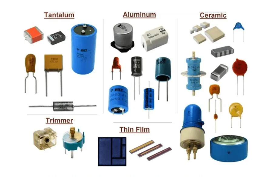
The selection of capacitor type significantly influences the performance of parallel configurations. Different capacitor technologies exhibit unique characteristics, including capacitance stability with temperature and frequency, equivalent series resistance (ESR), and voltage/current handling capabilities, all of which are crucial in parallel circuit applications. Careful consideration of these factors is vital for optimized circuit performance.
| Capacitor Type | Key Characteristics | Suitability for Parallel Use | Considerations |
|---|---|---|---|
| Ceramic | Low ESR, good high-frequency performance, small size, wide range of capacitance values | Excellent for decoupling and high-frequency filtering | Capacitance varies with temperature and voltage, may be prone to piezoelectric effects. |
| Electrolytic | High capacitance per volume, polarized, higher ESR than ceramic | Suitable for bulk energy storage and low frequency applications where high capacitance is required. | Polarity must be observed, limited frequency range, and potential for electrolyte leakage or drying over time. |
| Film | Good stability, low ESR, high voltage ratings, moderate capacitance range | Excellent choice for power applications and timing circuits where stability is paramount. | Larger size compared to ceramic capacitors, more expensive. |
When implementing capacitors in parallel, ensure that the individual components have matched voltage ratings, temperature coefficients, and appropriate ESR ratings for the specific use case. This ensures that the load is evenly distributed across the multiple capacitors.
Frequently Asked Questions About Capacitors in Parallel Circuits
This section addresses common queries regarding capacitors connected in parallel, providing clear and concise answers to enhance understanding of their behavior and application.
- What happens when capacitors are connected in parallel?
When capacitors are connected in parallel, the total capacitance of the circuit increases. Each capacitor stores a charge proportional to the applied voltage, and the total charge stored is the sum of the charges stored by each capacitor. The voltage across each parallel capacitor is the same. - What is the formula for calculating total capacitance when capacitors are in parallel?
The total capacitance (C_total) for capacitors in parallel is calculated by summing the individual capacitances: C_total = C1 + C2 + C3 + ... + Cn. This means that each capacitor directly contributes to the total ability of the circuit to store charge. - What are the fundamental rules for capacitors in parallel circuits?
The primary rules for parallel capacitors are: 1) The voltage across each capacitor is the same, and is equal to the source voltage; 2) The total capacitance is the sum of the individual capacitances; and 3) The total charge stored is the sum of individual charges on each capacitor. - How do you connect two capacitors in parallel practically?
To connect two capacitors in parallel, simply connect the positive terminals of both capacitors together, and connect the negative terminals together. These combined positive and negative connections are then connected to your power source or circuit terminals. It's critical to ensure that the capacitors are rated for the operating voltage to prevent damage. - How do variations in manufacturing and tolerances affect parallel capacitor behavior?
Manufacturing tolerances result in slight variations in the capacitance of each component. When capacitors are connected in parallel, these variations affect the amount of charge stored by each capacitor, but the overall system behaves according to total combined capacitance. It is generally good practice to consider the rated tolerances of all components and select components that are within acceptable limits of variation for the application. - Does connecting capacitors in parallel increase the current handling capacity?
Yes, connecting capacitors in parallel increases the current handling capacity. The total current the circuit can handle is effectively divided among the parallel capacitors. This parallel configuration allows the circuit to handle higher currents than a single capacitor could on its own and also reduces the equivalent series resistance. - Is there a limit to how many capacitors you can connect in parallel?
While there's no strict limit to the number of capacitors you can connect in parallel, practical considerations like space, cost, and potential for variations in manufacturing tolerances often become limiting factors. Additionally, at very high frequencies, parasitic inductances from the connections between capacitors can impact circuit performance.
Advantages and Disadvantages of Parallel Capacitor Configurations
Connecting capacitors in parallel offers several benefits, primarily increasing the overall capacitance of a circuit, which is crucial for energy storage and filtering applications. However, this configuration also introduces certain drawbacks, particularly concerning circuit complexity. It's essential to weigh these factors carefully when designing electronic systems.
| Feature | Advantages | Disadvantages |
|---|---|---|
| Total Capacitance | Increases the total capacitance by the sum of the individual capacitor values. | Requires more physical space for multiple components. |
| Equivalent Series Resistance (ESR) | Reduces overall ESR, leading to lower losses and improved high-frequency performance. | Increased physical circuit complexity, can impact manufacturing costs and reliability. |
| Current Handling | Increases the capacity to handle larger currents compared to a single capacitor. | Capacitor variations due to manufacturing tolerance can result in uneven current sharing |
| Cost | Can use smaller, lower-cost capacitors to achieve higher capacitance compared to using single large capacitor. | Potentially higher component count can lead to increased circuit footprint and assembly costs. |
| Reliability | Potential for redundancy; failure of one capacitor may not cause complete circuit failure. | Individual capacitor failure can impact overall circuit performance. |
When considering parallel configurations, careful selection of capacitor types and values is essential to maximize the benefits and avoid the disadvantages. It's also crucial to take into account the manufacturing tolerances of the capacitors; uneven capacitance values or manufacturing variations can impact performance.
In practical applications, you might use parallel capacitors for increased capacitance in power supply filtering, where the increased capacitance is needed for filtering ripple or in decoupling applications to improve signal integrity by handling transient currents. Consider alternatives like supercapacitors if very high capacitance is needed in a small area and series configurations if high voltage is required.
Parallel Capacitor vs Series Capacitor: A Comparative Analysis
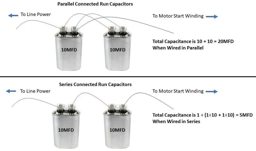
Understanding the distinctions between parallel and series capacitor configurations is crucial for effective circuit design. While parallel configurations increase total capacitance and current handling capabilities, series configurations are used to handle higher voltages. This section provides a comparative analysis of these two common arrangements, detailing their key differences in terms of total capacitance, voltage handling, and suitable application areas.
| Feature | Parallel Capacitors | Series Capacitors |
|---|---|---|
| Total Capacitance | Sum of individual capacitances (C_total = C1 + C2 + ... + Cn) | Reciprocal of the sum of reciprocal capacitances (1/C_total = 1/C1 + 1/C2 + ... + 1/Cn) |
| Voltage Handling | Voltage across each capacitor is the same as the source voltage. | Voltage is divided among the capacitors based on their capacitance. |
| Current Handling | Total current is divided among the capacitors | Current is the same through all capacitors |
| Application Areas | Increasing capacitance, smoothing voltage in power supplies, decoupling in digital circuits. | Voltage multiplication, high voltage applications |
| Equivalent Series Resistance (ESR) | ESR is reduced, improving high-frequency performance | ESR increases, which can be a disadvantage in some applications |
Capacitors in parallel are essential in modern electronics, offering a way to increase capacitance and manage high currents. By connecting capacitors in parallel, engineers can optimize circuit performance and meet the demands of various applications, much like how using multiple instruments can enrich the sound of a band. Understanding these parallel configurations is crucial for designing efficient and reliable electronic systems, and as technology advances, further explorations of parallel capacitor networks promise to enhance future innovations. The ability to precisely tailor capacitor networks using parallel configuration is a testament to the power and flexibility of foundational electrical engineering principles.