Unlocking the Power: Understanding Basic Electric Circuits
In a world powered by electricity, basic electric circuits are the unsung heroes, silently enabling the technology that surrounds us. From the simplest light bulb to the most complex computer, they all rely on the fundamental principles of a circuit. Understanding these basic electric circuit is key to understanding how electrons flow, how energy is transferred, and how our devices work. This article dives into the essential components, types, and the core concepts needed to grasp the fundamentals of a basic electric circuit, making them accessible to everyone.
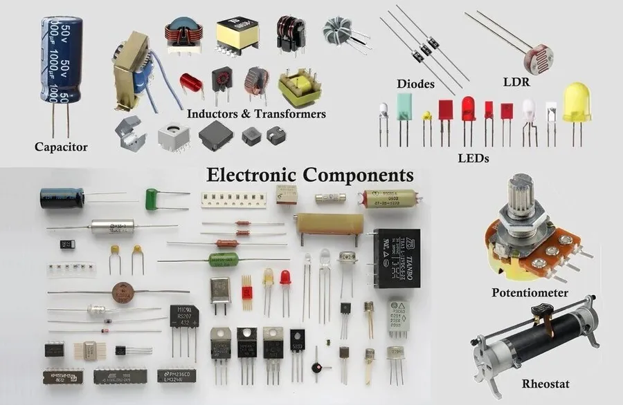
Core Components of a Basic Electric Circuit
A basic electric circuit, at its core, is a closed loop that facilitates the flow of electrical charge, enabling the operation of various devices and systems. This fundamental system comprises four essential components: a power source, conductors, loads, and a switch. These elements work in concert to create a path for electrons to move, thereby converting electrical energy into other forms of energy.
- Power Source
The power source is the origin of electrical energy within a circuit. Common examples include batteries, which convert chemical energy into electrical energy, and generators, which transform mechanical energy into electrical energy. The power source provides the necessary voltage that drives the current flow. - Conductors
Conductors are materials that facilitate the flow of electric current with minimal resistance. Typically, metals such as copper and aluminum are used for this purpose. These materials, commonly in the form of wires, provide the pathways for electrons to move throughout the circuit. - Loads
Loads are components within a circuit that utilize electrical energy to perform a specific function. Resistors, which limit current flow, and light bulbs, which convert electrical energy into light, are common loads. These components transform electrical energy into another usable form, which is the intended function of the circuit. - Switch
A switch is a device used to control the flow of current in a circuit. It can open or close the circuit, starting or stopping the flow of current. Switches provide a convenient way to turn devices on and off and control the energy flow, which are essential for safe and efficient operation of a circuit.
The Role of Voltage, Current, and Resistance
Understanding the fundamental relationship between voltage, current, and resistance is crucial for comprehending how basic electric circuits function. Voltage acts as the driving force, pushing electrical charges; current is the rate at which these charges flow; and resistance impedes this flow. These three parameters are intrinsically linked and governed by Ohm's Law, a cornerstone of circuit analysis.
| Parameter | Symbol | Unit | Description |
|---|---|---|---|
| Voltage | V | Volts (V) | The electrical potential difference or 'pressure' that drives current flow. |
| Current | I | Amperes (A) | The rate of flow of electric charge through a conductor. |
| Resistance | R | Ohms (Ω) | The opposition to the flow of current in a circuit. |
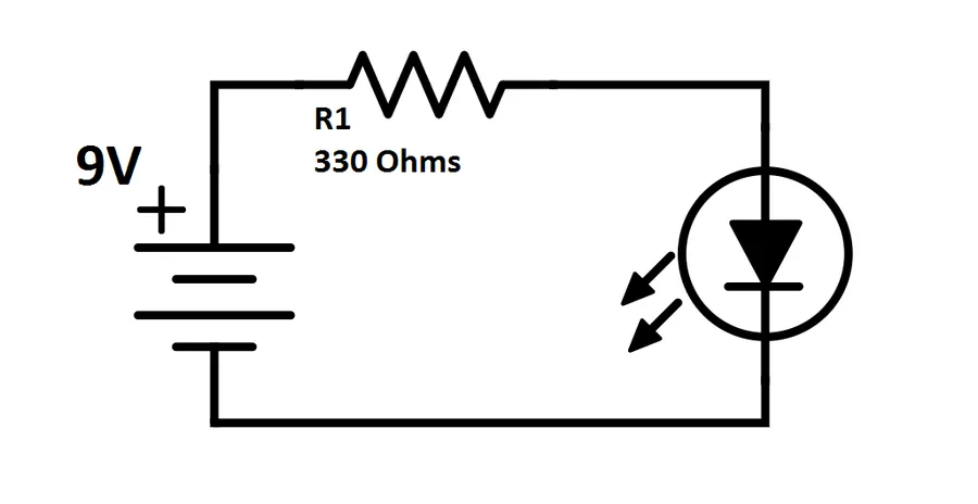
Ohm's Law mathematically defines the relationship between voltage (V), current (I), and resistance (R). It states that the current through a conductor between two points is directly proportional to the voltage across the two points, and inversely proportional to the resistance of the conductor. The equation is commonly expressed as V = IR.
Using Ohm's Law, we can calculate any one of these parameters if the other two are known. For example, if a 10-ohm resistor is connected to a 12-volt source, the current flowing through it can be calculated as I = V/R = 12V / 10Ω = 1.2A.
The interplay of voltage, current, and resistance dictates circuit behavior. A higher voltage, with resistance being constant, results in greater current flow. Conversely, a higher resistance, with constant voltage, reduces the current flow. This fundamental understanding is essential for designing, analyzing, and troubleshooting any electric circuit.
Types of Basic Electric Circuits: Series vs. Parallel
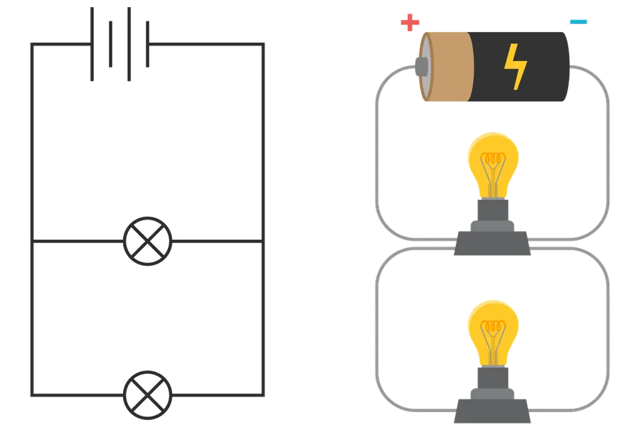
Basic electric circuits are fundamentally configured in two ways: series and parallel. Understanding these configurations is crucial as it dictates how current flows and voltage is distributed within the circuit. The choice of circuit type depends largely on the application and the desired behavior of the connected components.
| Feature | Series Circuit | Parallel Circuit |
|---|---|---|
| Component Connection | End-to-end, forming a single path | Side-by-side, providing multiple paths |
| Current Flow | Same current through all components | Current divides across different branches |
| Voltage Distribution | Voltage divides across components | Same voltage across all components |
| Total Resistance | Sum of individual resistances | Reciprocal of the sum of reciprocals |
| Circuit Failure | Failure of one component interrupts the entire circuit | Failure of one branch does not interrupt other branches |
| Typical Applications | Simple lighting chains, basic sensors | Household wiring, power distribution |
In a series circuit, the current remains constant throughout the entire circuit, however, each component consumes a portion of the overall source voltage. In a parallel circuit, voltage remains constant across all branches, with the total current being divided across each of the multiple paths. The total resistance in a series circuit is the simple sum of all resistances, but the calculation for parallel circuits involves the reciprocal of the sum of the reciprocals of the individual resistances.
Circuit Diagrams and Schematics
Circuit diagrams, also known as schematics, are standardized graphical representations of electrical circuits. They utilize specific symbols to denote components, enabling clear communication and analysis of circuit designs, simplifying both understanding and construction.
| Component | Schematic Symbol | Description |
|---|---|---|
| Resistor | A zigzag line | Limits current flow |
| Capacitor | Two parallel lines | Stores electrical energy in an electric field |
| Inductor | A coiled line | Stores electrical energy in a magnetic field |
| Diode | Triangle pointing to a line | Allows current flow in one direction |
| Battery | A long line and a short line | Provides voltage/power |
| Switch | A broken line with a connector | Controls the flow of current |
| Ground | Three lines decreasing in size | Reference point of zero voltage |
These standard symbols ensure that electrical engineers and technicians worldwide can readily understand and build circuits based on the same schematics. The diagrams facilitate the analysis of electrical circuits and the understanding of their functionality.
Basic Electric Circuit Laws: Kirchhoff's Laws
Kirchhoff's Laws are foundational principles for analyzing electric circuits, providing a structured approach to understanding current and voltage distribution within complex networks. These two laws, Kirchhoff's Current Law (KCL) and Kirchhoff's Voltage Law (KVL), enable precise calculation of circuit behavior where Ohm's Law alone is insufficient.
| Law | Description | Application |
|---|---|---|
| Kirchhoff's Current Law (KCL) | The sum of currents entering a junction (or node) is equal to the sum of currents leaving that junction. | Analyzing current distribution at a node in a circuit. |
| Kirchhoff's Voltage Law (KVL) | The sum of voltage drops around a closed loop in a circuit is equal to the sum of voltage rises in that loop. (or The algebraic sum of all voltages around any closed loop is zero) | Analyzing voltage distribution in a closed loop of a circuit. |
By applying KCL and KVL, engineers and technicians can solve for unknown currents and voltages within intricate circuits that cannot be simplified using basic series and parallel equivalent resistance rules. These laws are essential for accurately predicting and managing the operation of a wide variety of electrical systems.
Practical Applications of Basic Electric Circuits

Basic electric circuits are the foundation of countless technologies we use daily. From the simple act of illuminating a room to the complex systems that power our vehicles and industries, these circuits are indispensable. Understanding their practical applications underscores their significance in modern life.
Here are several key areas where basic electric circuits are utilized:
- Home Lighting
A basic series or parallel circuit connects light fixtures to the power source, enabling illumination in homes and buildings. Switches control the current flow, allowing users to turn lights on and off. - Electronic Devices
Smartphones, computers, and televisions all rely on intricate networks of basic circuits to perform their various functions. These circuits include resistors, capacitors, diodes, and transistors organized into complex layouts. - Vehicle Electrical Systems
Automobile electrical systems utilize both series and parallel circuits to power lighting, ignition, and control systems. The car battery serves as the power source, and various circuits power headlights, taillights, the starter motor, and the infotainment system. - Industrial Machinery
Large-scale industrial equipment incorporates complex circuits to control motors, sensors, and actuators. These circuits enable automated processes and precise manufacturing operations. - Power Distribution
The distribution of electricity from power plants to homes and businesses depends on electrical circuits. These networks can involve high-voltage transmission lines, transformers, and distribution systems. - Medical Equipment
Numerous medical devices, such as diagnostic tools and life support systems, depend on basic electrical circuits. These devices use circuits to provide precise measurements, control various actuators, and deliver life-saving therapies.
These examples demonstrate the widespread and essential nature of basic electric circuits. The underlying principles of voltage, current, and resistance apply to all these applications, despite variations in complexity and scale.
| Application | Circuit Type | Key Components |
|---|---|---|
| Home Lighting | Series or Parallel | Switches, Light Bulbs, Wires, Power Source |
| Smartphones | Complex Integrated Circuits | Transistors, Resistors, Capacitors, Diodes |
| Vehicle Systems | Mixed Series and Parallel | Battery, Fuses, Relays, Lights, Ignition System |
| Industrial Equipment | Complex Networks | Motors, Sensors, Actuators, Control Units |
| Power Distribution | Complex Grids | Transformers, Transmission Lines, Substations |
| Medical Devices | Precision Circuits | Sensors, Actuators, Microcontrollers, Power Sources |
Troubleshooting Basic Electric Circuits
Effective troubleshooting of basic electric circuits is crucial for both practical applications and safety. This section provides a structured approach to identifying and resolving common circuit faults, emphasizing the importance of methodical testing and adherence to safety protocols when working with electrical systems.
- Common Circuit Faults
Common issues in basic circuits include open circuits (where the path is broken), short circuits (where current flows through an unintended path with minimal resistance), and component failures (such as a resistor exceeding its rated power or a switch malfunctioning). Each presents a distinct behavior and requires targeted diagnostic approaches. - Essential Tools for Troubleshooting
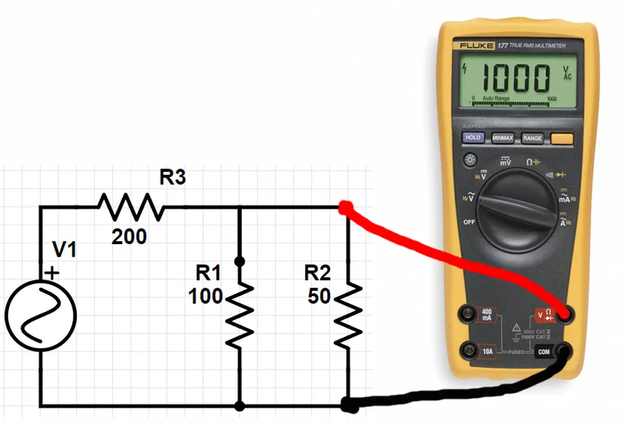
A multimeter is indispensable for measuring voltage, current, and resistance. Other useful tools include wire strippers, screwdrivers, and insulated test leads. Understanding how to properly use these tools is as important as having them. - Systematic Troubleshooting Procedure
Begin with a visual inspection for obvious issues, such as loose connections, broken wires, or burnt components. Then use a multimeter to measure voltage at various points in the circuit to pinpoint the location of a fault, such as testing for continuity, voltage drops and unexpected shorts. Work methodically and logically, and do not change multiple components at once unless you need to. - Open Circuit Diagnosis
An open circuit prevents current flow. Check for continuity across each segment of the circuit. If a component measures infinite resistance, it is likely the open point. Inspect solder joints, wires, switches and any device that can interrupt the signal. A systematic approach to each segment will reveal the point. - Short Circuit Diagnosis
A short circuit usually results in excessive current flow, which can cause heat and further damage. Look for unintended direct connections across the circuit, such as exposed wires touching. A short should be easy to find, if you can isolate the point of the short, you can repair it. - Component Failure Diagnosis
Components can fail due to exceeding voltage or current rating. Resistance values can change drastically, causing issues. Test individual components to check for accurate measurements, if they are out of spec, then they must be replaced. - Safety Precautions
Always disconnect the power source before performing any tests or repairs. Use insulated tools and avoid working in wet environments. When working with live circuits, be mindful of the potential for electric shock; proper procedures and testing equipment is essential. Prioritizing safety is always the primary concern.
Frequently Asked Questions about Basic Electric Circuits
This section addresses common inquiries regarding basic electric circuits, aiming to provide a clear and concise understanding of fundamental principles, design considerations, component selection, and safe practices.
- What is the fundamental definition of a basic electric circuit?
A basic electric circuit is a closed loop that allows electric charge to flow, typically comprising a power source, conductors, and a load. Without a complete loop, current cannot flow, and the circuit is considered open. - What are the essential components required to build a basic electric circuit?
The fundamental components of a basic electric circuit include a power source (e.g., a battery or generator) to provide voltage, conductors (wires) to facilitate the flow of current, a load (e.g., a resistor or light bulb) to consume electrical energy, and often a switch to control the circuit's on/off state. These components must form a closed path for current to flow. - How can I differentiate between a series circuit and a parallel circuit?
In a series circuit, components are connected end-to-end, forming a single path for current flow. The current is the same through all components, while the voltage is divided across them. In a parallel circuit, components are connected side-by-side, providing multiple paths for current. Voltage is consistent across all branches, while current is divided among them. - What are the three fundamental types of electrical circuits?
While series and parallel are the primary classifications, the types can also be considered as: a) *Closed Circuit*: This allows for continuous current flow, b) *Open Circuit*: This prevents current flow due to a break in the path, and c) *Short Circuit*: This provides a low-resistance path, potentially causing excessive current. - What are the necessary conditions for a simple circuit to function correctly?
For a simple circuit to function correctly, there are three key requirements: a complete conductive path, a sufficient voltage source to provide the driving force for charge flow, and an appropriate load to consume the electrical energy. Any break or insufficient voltage can impede operation. - What is Ohm's Law, and how is it applied to circuit analysis?
Ohm's Law (V=IR) establishes the relationship between voltage (V), current (I), and resistance (R) in a circuit. It states that the voltage across a resistor is directly proportional to the current flowing through it. This relationship is fundamental for calculating current, voltage, or resistance within a circuit. - How do Kirchhoff's laws aid in analyzing complex circuits?
Kirchhoff's Current Law (KCL) states that the total current entering a junction must equal the total current leaving it. Kirchhoff's Voltage Law (KVL) states that the sum of voltage drops around a closed loop must equal the total voltage supplied. These laws are essential tools to analyze complex circuits involving multiple loops and junctions. KCL deals with current division at nodes, and KVL deals with voltage drops in closed paths.
Advanced Circuit Concepts: Stepping Beyond Basics
While a solid grasp of basic electric circuits is essential, the world of electronics extends far beyond simple DC configurations. This section provides a concise overview of advanced concepts, including alternating current (AC) circuits, reactive components like capacitors and inductors, and semiconductor devices like transistors, which form the bedrock of modern electronics. These concepts build upon the foundations laid by basic circuits and offer a gateway to understanding more complex electronic systems.
- Alternating Current (AC) Circuits
Unlike direct current (DC) where current flows in one direction, AC circuits involve current that periodically reverses direction. This is the type of current used in most household electrical systems. AC circuit analysis requires understanding concepts like frequency, impedance, and phase. - Reactive Components: Capacitors and Inductors
Capacitors and inductors are circuit elements that exhibit a time-dependent relationship between voltage and current. Capacitors store energy in an electric field and resist changes in voltage, while inductors store energy in a magnetic field and resist changes in current. These components play a key role in AC circuit behavior and signal processing. - Semiconductor Devices: Transistors
Transistors are fundamental semiconductor devices that act as electronic switches and amplifiers. They are the building blocks of integrated circuits (ICs) and modern electronic devices. Understanding transistor operation is crucial for delving into advanced electronics. - Signal Processing
Advanced circuits often manipulate signals, using concepts like filtering, modulation, and amplification. This involves using combination of different circuit components and often sophisticated mathematical techniques. - Operational Amplifiers (Op-Amps)
Op-Amps are versatile integrated circuits used for amplifying signals, performing mathematical operations, and implementing various other functions in analog and mixed-signal circuits. They are vital components in audio, instrumentation, and control systems.
Understanding basic electric circuits is the cornerstone of all electrical and electronic engineering. From the simple flow of electrons through a wire to the intricate networks of modern devices, the same principles apply. By mastering the concepts of voltage, current, resistance, and the core components, we unlock the ability to understand, design, and troubleshoot a wide range of electrical systems. The journey doesn’t stop here; with this foundational knowledge, you can continue to explore more complex circuit designs and advanced electrical engineering topics, powering your understanding of how our world works.