Unlocking the Secrets of the 0 Ohm Resistor: A Comprehensive Guide
In the intricate world of electronics, components like resistors are fundamental. But what about a resistor with zero ohms? The concept might seem counterintuitive, like a square circle, but the 0 ohm resistor plays a crucial role in circuit design. This seemingly simple component acts as a bridge, allowing designers flexibility in PCB layout, circuit testing, and more. This article will explore the function, use cases, and benefits of this unique component, moving from simple connections to complex circuit designs.
What Exactly is a 0 Ohm Resistor?
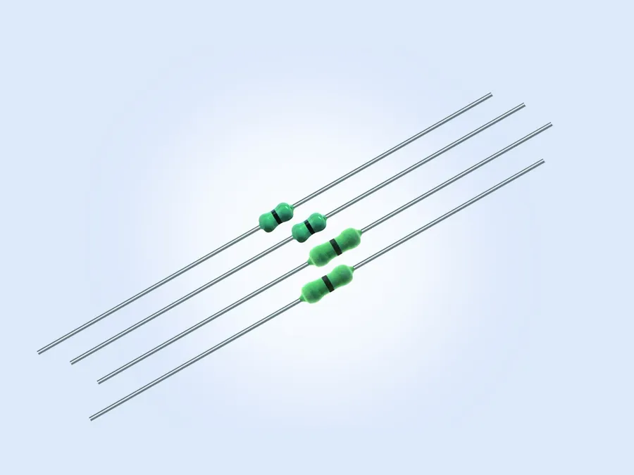
A 0 ohm resistor is a surface mount or leaded component that, while appearing as a standard resistor, serves as a direct connection path, with a nominal resistance very close to zero ohms. It's not a perfect conductor, but rather a specialized component designed for automated assembly processes on Printed Circuit Boards (PCBs), mimicking the form factor of a typical resistor. Crucially, these devices have a very low, but non-zero resistance, which is essential in understanding their use and limitations.
Why Use a 0 Ohm Resistor Instead of a Wire?
While a simple wire might seem like a direct substitute for a 0 ohm resistor, the latter offers distinct advantages, particularly in automated manufacturing environments. The key differentiation lies not in their electrical conductivity, which is nearly identical, but rather in their form factor and compatibility with automated assembly processes commonly used in printed circuit board (PCB) production.
| Feature | 0 Ohm Resistor | Simple Wire |
|---|---|---|
| Automated Assembly | Designed for pick-and-place machines; easily placed with high precision. | Requires manual placement or specialized equipment, less efficient in automated lines. |
| Reflow Soldering Compatibility | Compatible with standard reflow soldering processes used for other surface mount components. | Usually requires separate soldering processes, making the manufacturing process more complex and time consuming. |
| Form Factor | Standardized component packages (SMD), uniform and reliable for placement. | May vary in size and form which can cause issues with automated placement. |
| Reliability | Consistent performance and placement due to standardized manufacturing processes. | Inconsistent if not carefully placed or soldered, can cause variable results. |
| Inventory and Stock Management | Managed as a standard component, consistent tracking and ordering is easily achieved. | Custom wire sizes would require individual management and ordering. |
| Cost | Economical at high volume, due to the automated manufacturing. | Potentially cheaper for single unit production, but more costly at scale. |
The use of 0 ohm resistors, therefore, streamlines the PCB manufacturing process by maintaining consistency and leveraging existing automated assembly infrastructure.
Key Applications of Zero-Ohm Resistors
Zero-ohm resistors, despite their seemingly paradoxical nature, serve critical functions in electronic circuit design. These components, designed with a nominal resistance of zero ohms, function as highly efficient circuit links. Their primary applications revolve around signal routing, configuration flexibility, circuit testing, and impedance management, offering a versatile solution to various design challenges.
- Signal Routing Jumpers
Zero-ohm resistors are frequently used as jumpers to route signals across different layers of a printed circuit board (PCB). In single-layer PCB designs, this eliminates the need for complex multi-layer boards and simplifies the layout. They act as temporary connections, making it easier to modify the circuit design as necessary. - Configuration Links
They function as configuration links, enabling different settings for the same PCB. By placing or removing these resistors, different circuit configurations can be easily implemented, allowing one PCB design to be used for multiple different functions, saving time and material costs. - Test Points for Debugging
Acting as test points, these components facilitate circuit debugging. The low resistance allows for accurate measurements using standard multimeters, enabling circuit integrity verification and testing of different segments. - Impedance Matching
While not their primary purpose, zero-ohm resistors can be used in some applications to match impedance within circuits. They provide a connection with minimal impedance that is still suitable for high-speed data transfer, ensuring that signal integrity is maintained and allowing efficient power transfer. They also provide a defined point in the circuit with minimal impedance, allowing for easier analysis and troubleshooting.
The Role of 0 Ohm Resistors in PCB Layout

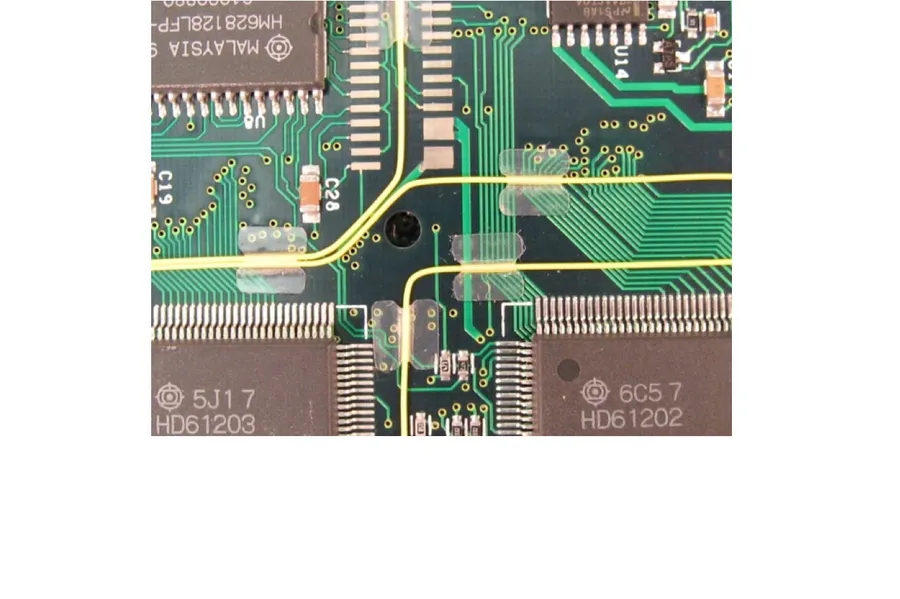
Zero-ohm resistors play a crucial role in simplifying Printed Circuit Board (PCB) design, primarily by enabling single-layer board implementations and providing routing flexibility. Their ability to bridge traces avoids the necessity for more complex and costly multilayer boards.
By effectively acting as a 'jumper' on a circuit board, zero-ohm resistors allow signal paths to cross over each other without creating a direct short. This is particularly useful when designing a single-layer PCB, as it avoids the need to route traces around obstacles or utilize vias, which are more complex and costly. This method simplifies PCB layout and reduces manufacturing cost by reducing the number of fabrication layers.
Additionally, the use of 0-ohm resistors makes it easier to change PCB configurations and prototypes without the need for board re-fabrication. If design changes are needed during testing and development, engineers can easily modify or remove 0 ohm resistors to adjust the circuit paths, avoiding time-consuming alterations of the base PCB layout. This flexibility can be critical in fast-paced product development cycles.
The utilization of 0-ohm resistors also allows for design flexibility by allowing traces to be placed in more logical and efficient configurations. This can lead to enhanced signal integrity and overall performance optimization of the designed circuitry. Such routing optimization is particularly beneficial when dealing with high-speed signals, where short and direct traces are critical to reduce signal losses.
0 Ohm Resistors as Test Points

Zero-ohm resistors, while primarily used for signal routing and circuit configuration, also serve a crucial role as test points on printed circuit boards (PCBs). Their low resistance allows them to be used to isolate and test sections of a circuit, offering an easily accessible way to probe and analyze circuit behavior during development, troubleshooting, and production.
By strategically placing these resistors at key locations in a design, engineers can quickly assess signal integrity, voltage levels, and current flow using a multimeter. This is particularly useful in debugging complex circuits where directly accessing a trace might be challenging.
The primary advantage of using 0-ohm resistors as test points is that they are designed to be easily placed using automated assembly machines. This makes it less labor-intensive to set up test points on production boards. Furthermore, these resistors have a minimal impact on the circuit performance when compared to other options, while providing a simple and reliable location for measurement.
- Ease of Access
Provides a readily available point to connect test probes, simplifying measurements. - Circuit Isolation
Allows engineers to effectively isolate specific sections of a circuit for targeted testing. - Minimal Impact
Due to their very low resistance, they have a negligible impact on circuit performance when used as test points. - Cost Effective
A cost-effective alternative to dedicated test point components for easy automated placement.
Zero-Ohm Resistors vs. Jumpers
Zero-ohm resistors and traditional wire jumpers serve the purpose of creating electrical connections on circuit boards, but they differ significantly in their application, particularly in high-volume manufacturing. While both provide a conductive path, 0-ohm resistors offer advantages tailored for automated assembly processes, whereas wire jumpers are more suited to manual or prototyping contexts.
| Feature | 0-Ohm Resistor | Wire Jumper |
|---|---|---|
| Assembly Method | Automated pick-and-place machines, reflow soldering | Manual placement, soldering, or mechanical connection |
| Production Volume | Ideal for mass production, high-volume assembly | Suitable for prototyping, low-volume or manual assembly |
| Placement Precision | Highly accurate placement by automated systems | Subject to human error and manual alignment |
| Reflow Soldering | Designed for reflow soldering processes | Not typically compatible with reflow; requires hand soldering or specialized connectors |
| Cost | Typically cost-effective for high volumes | May be more expensive in terms of labor and manual placement |
| Mechanical Robustness | Typically more robust when surface mounted | Can be prone to bending, displacement, or accidental damage |
| Reliability | Consistent contact and solder joints due to automated processes | Susceptible to inconsistent soldering, improper connections |
| Standardization | Available in standard surface-mount packages and sizes, common footprint | Often custom or application specific, lack of standardization |
In summary, the choice between 0-ohm resistors and wire jumpers hinges on the application. For large-scale manufacturing where efficiency, accuracy, and automation are paramount, 0-ohm resistors are the clear choice. Wire jumpers remain appropriate for smaller scale prototyping or situations where manual placement and customization are required.
Frequently Asked Questions About 0 Ohm Resistors
This section addresses common queries about 0 ohm resistors, clarifying their functionality and application in electronic circuits. We aim to provide concise, technically accurate answers to these frequently asked questions.
- Can a 0 ohm resistor act as a fuse?
While a 0 ohm resistor is not designed to function as a fuse, it does have a limited current handling capacity. Exceeding this rating can cause it to fail open, effectively interrupting the circuit, but it is not a reliable or designed method of overcurrent protection. Dedicated fuses or circuit breakers are designed to fail reliably at specific current levels, providing more predictable and dependable overcurrent protection compared to a 0-ohm resistor. - What is the typical tolerance range of a 0 ohm resistor?
Although described as 0 ohms, these resistors do have a small but measurable resistance. The tolerance is usually expressed as a maximum resistance value rather than a percentage. A typical tolerance might be described as less than 0.05 ohms or even lower, depending on the manufacturer and specific part. The key is that it is a very low resistance value that is suitable for use as a jumper, not that is has zero resistance - How much current can a 0 ohm resistor handle?
The current handling capacity of a 0 ohm resistor is dependent on its physical size and construction, which dictates how much power it can dissipate as heat. Larger package sizes, like 0805 or 1206, can typically handle higher currents, from 1 amp up to 2 or 3 amps, while smaller package sizes like 0402 and 0201, can only handle lower currents. Always refer to the manufacturer's datasheet for the specific current rating of the selected resistor size and series. - What are the standard sizes of 0 ohm resistors?
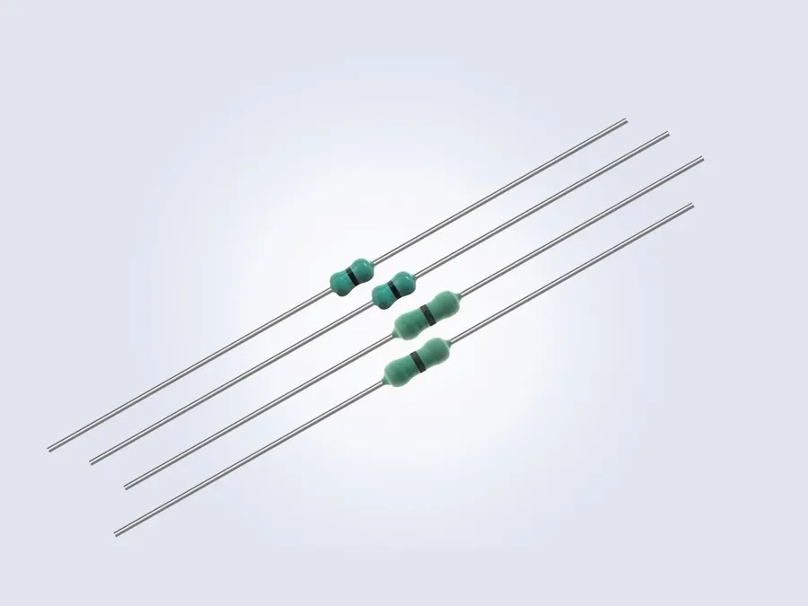
Zero-ohm resistors are available in many surface mount (SMD) package sizes, such as 0201, 0402, 0603, 0805, and 1206. The sizes indicate their physical dimensions in inches. Leaded varieties are also available, which are used for through-hole mounting. The selection of size depends on the current requirements and the overall space constraints on the printed circuit board. - Is it possible to have a perfect 0 ohm resistor?
No, a perfect 0 ohm resistor is physically impossible in practical applications. All physical materials have some inherent resistance. The term '0 ohm resistor' refers to a component with a very low resistance (typically less than 0.05 ohms), designed to act as a link or jumper within a circuit, rather than having zero resistance. - What is the lowest ohm resistor available?
While '0 ohm' resistors are functionally low, they aren't the lowest achievable resistance. Some precision resistors with values in the milliohm range (e.g., 0.001 ohms or even lower) are available for specialized applications. However, these are very different devices intended for very specific purposes, like current sensing, and have different performance characteristics than a 0 ohm resistor. - Why is a 0 ohm resistor used over a direct short?
While it might seem that a direct short is the same as a 0-ohm resistor, the 0 ohm resistor is specifically designed for automated assembly processes, being automatically placed and soldered by pick and place machines the same as other passive components. A direct short would involve manually soldering a wire which is not conducive to the high throughput of production circuit boards. It simplifies PCB manufacturing and testing processes.
Understanding the Specifications: 0 Ohm Resistor Markings and Packages
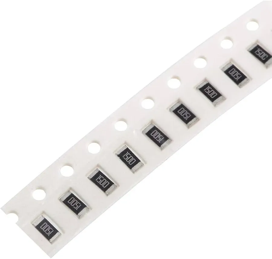
Zero-ohm resistors, while appearing deceptively simple, require careful consideration of their markings, package types, and power ratings for successful integration into electronic designs. Understanding these specifications ensures correct selection and reliable performance, crucial for any application. These resistors, often serving as convenient links or jumpers, come in various forms adapted for different assembly methods and operational demands.
| Feature | Description | Importance |
|---|---|---|
| Markings | Usually a single '0' or a series of zeros (e.g., '000') | Identifies the component as a 0-ohm resistor, preventing misidentification with other components. The marking may also indicate the manufacturers part number. |
| SMD Packages | Surface Mount Devices, with common sizes like 0402, 0603, 0805, 1206 | Ideal for automated assembly lines and high-density PCBs. Size choice depends on PCB space and power requirements. |
| Leaded Packages | Traditional through-hole components, axial or radial leads | Suitable for prototyping and less automated environments. Provides robust connections but are generally larger than SMD. |
| Power Rating | Indicates the maximum power a resistor can dissipate without overheating. | Critical for preventing device failure, especially when higher current is involved. Selection must exceed anticipated current draw. |
| Current Handling Capacity | Refers to the maximum continuous current the component can safely handle | Essential to avoid failure and ensure the 0-ohm resistor acts as intended, not as a fuse. |
| Operating Temperature Range | The range of temperature over which the resistor can safely function | Critical for high reliability in industrial and automotive applications, where temperature may vary wildly. Must match the application conditions. |
Selecting the correct package and size for a zero-ohm resistor depends on several key factors, particularly the assembly method and space constraints of the circuit design. Surface mount (SMD) packages such as 0402, 0603, 0805, and 1206 are commonly used in high-volume production due to their compatibility with automated pick-and-place machines and reflow soldering processes. These smaller packages are ideal for dense PCB layouts where space is limited.
In contrast, leaded packages, including axial and radial lead resistors, are generally preferred in environments where manual assembly or prototyping is required due to the robustness of through hole connections. It's important to note that each package has different power handling capabilities, which influences design choices when selecting between packages. The SMD packages are generally lower power, while the leaded packages have the potential for more power handling, although this is not always the case, and the specifications must be checked to ensure suitability for application.
The selection of a 0-ohm resistor is also closely tied to its intended purpose within a design. For simple signal routing or creating configuration links, smaller package sizes might be adequate. However, when a 0-ohm resistor serves as a test point or is part of a high-current path, a larger package size with a higher power rating might be necessary to manage the current flow without failure. Always refer to the manufacturer's datasheet to ensure that the component meets the requirements of the application.
The 0 ohm resistor, though seemingly a simple component, is a versatile tool in electronics. It is not just a wire, but it is an important component in modern PCB design and testing. It facilitates PCB layout by acting as a zero ohm jumper, makes circuit testing easier and allows for configurable designs. Understanding the purpose and application of the 0 ohm resistor provides insights to more efficient circuit boards and makes for quicker debugging. As we move towards more complex and miniaturized circuits, it will become even more important in electronics design.