Unlocking the Secrets of the 1N4007 Diode: A Comprehensive Guide
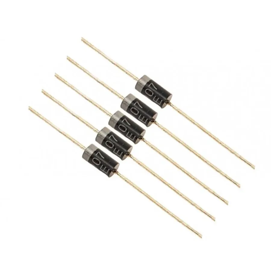
The 1N4007 diode, a tiny but mighty component, is a cornerstone in countless electronic devices. Like a one-way street for electricity, this diode ensures current flows in the intended direction. From simple power supplies to complex circuits, the 1N4007 plays a vital role, showcasing how fundamental components underpin modern technology. This article will delve deep into the world of the 1N4007, dissecting its specifications, applications, and significance, so you'll understand its power and potential.
Understanding the 1N4007 Diode: Basics and Functionality
The 1N4007 diode is a fundamental semiconductor device primarily employed as a rectifier, allowing electrical current to flow in one direction while blocking it in the opposite direction, this behavior is crucial for converting AC power to DC power in various electronic applications. Its core function stems from the unique properties of a P-N junction formed by doping silicon, creating regions of differing charge carrier concentrations. This structure facilitates a low resistance path for current flow when forward biased and very high resistance when reverse biased.
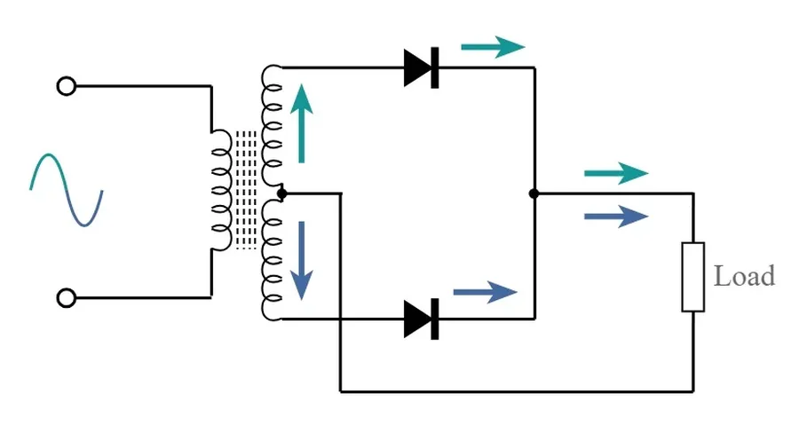
At its heart, a diode is a two-terminal electronic component. When the anode (positive terminal) is at a higher potential than the cathode (negative terminal), the diode is forward biased, allowing current to flow. Conversely, when the cathode is more positive than the anode, the diode is reverse biased, impeding current flow. This unidirectional characteristic is essential in rectifier circuits, where alternating current (AC) needs to be transformed into direct current (DC). The 1N4007, commonly used as a rectifier, achieves this AC-to-DC conversion efficiently.
1N4007 Diode Specifications: Voltage, Current, and Temperature

The 1N4007 diode is a robust and widely used rectifier diode, characterized by specific electrical parameters critical to its functionality. These parameters dictate its performance in various applications, making understanding them essential for proper circuit design and operation. Key specifications include its maximum forward current, peak reverse voltage, and operating temperature ranges, all of which influence its reliability and suitability for different operating conditions.
| Parameter | Value | Description |
|---|---|---|
| Maximum Average Forward Current (IF(AV)) | 1.0 Ampere | The maximum average current the diode can handle in the forward direction without damage. This is measured over a full cycle of AC at a specific temperature. |
| Peak Repetitive Reverse Voltage (VRRM) | 1000 Volts | The maximum reverse voltage the diode can withstand repeatedly without breaking down. Exceeding this can lead to diode damage and failure. |
| Peak Forward Surge Current (IFSM) | 30 Amperes | The maximum non-repetitive peak current the diode can withstand for a short period. This value is important when considering inrush currents upon start-up. |
| Forward Voltage Drop (VF) | 1.1 Volts (typical at 1A) | The voltage drop across the diode when conducting in the forward direction. This is not constant and increases with forward current. It is typically specified at the maximum forward current of 1A |
| Operating Temperature Range (TJ) | -55°C to +175°C | The range of ambient temperatures within which the diode can safely operate. Operation outside this range can lead to reduced performance and reliability. |
| Storage Temperature Range (TSTG) | -55°C to +175°C | The range of ambient temperatures at which the diode can be safely stored without performance degradation. |
| Reverse Leakage Current (IR) | 5 µA (typical at 1000V) | The small amount of current that flows through the diode in the reverse direction. This current is ideally zero, but is typically specified at the rated peak reverse voltage. |
1N4007 Diode Pinout Configuration and Identification
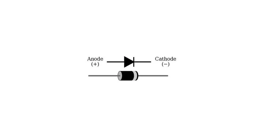
The 1N4007 diode, like most diodes, is a two-terminal semiconductor device possessing an anode (+) and a cathode (-). Understanding the pinout configuration and identifying these terminals is critical for correct circuit implementation. The anode and cathode orientations dictate the direction of current flow through the diode, crucial to the rectification process.
The 1N4007 diode's physical package typically includes a band marking on one end, which helps in the determination of each pin. The side of the diode with the band indicates the cathode (negative terminal), while the opposite side corresponds to the anode (positive terminal).
- Anode (+)
The anode is the terminal where the current enters the diode. It is the positive side of the diode. - Cathode (-)
The cathode is the terminal where current exits the diode. It is the negative side of the diode, identified by the band on the diode's body.
The physical marking, which is typically a silver or white band printed on the body of the diode, is the easiest and most reliable way to differentiate the cathode from the anode.
Applications of the 1N4007 Diode: Where It Shines
The 1N4007 diode, a workhorse in electronics, is primarily used for its rectification capabilities, efficiently converting AC to DC power. However, its applications extend far beyond simple power conversion, finding utility in various protection and signal conditioning circuits. Its robust specifications make it a versatile component in many designs.
- Power Rectification
The most common application for the 1N4007 is converting alternating current (AC) to direct current (DC). This is crucial in power supplies, where the diode allows current to flow in only one direction, effectively 'rectifying' the AC input. - Free-Wheeling Diode (Flyback Diode)
In inductive circuits, such as those involving relays or motors, the 1N4007 acts as a 'free-wheeling' or 'flyback' diode. When the current through an inductor is interrupted, the collapsing magnetic field induces a voltage spike. The 1N4007 provides a path for this current, protecting sensitive components from damage. - Overvoltage Protection
The 1N4007 can be used as a basic form of overvoltage protection. By connecting it in reverse bias across a sensitive component, it will not conduct under normal conditions. However, if an overvoltage condition occurs, the diode will start conducting, shunting the excess current and preventing damage to the protected component. This is not as precise as a Zener diode, but is adequate for many less critical scenarios. - Signal Demodulation
The 1N4007 diode can be utilized in simple AM radio demodulation circuits. It acts as a rectifier, extracting the audio signal from the modulated carrier wave. While more specialized diodes are commonly used for high-fidelity applications, the 1N4007 can serve in basic demodulation circuits. - General Purpose Switching
While not its primary function, the 1N4007 can be used as a general-purpose switching element in low-frequency circuits. The diode will be forward-biased when the voltage is applied and it will be reverse biased when the voltage is reversed. This binary operation makes it useful in basic switching circuits.
1N4007 Diode vs. Other Diodes: A Comparative Analysis
The 1N4007 diode is a widely used rectifier diode, but it's essential to understand how it compares to other common diodes. This section provides a detailed comparison with other popular diodes like the 1N4001 and 1N4148, highlighting their differences in specifications and typical applications.
| Characteristic | 1N4007 | 1N4001 | 1N4148 |
|---|---|---|---|
| Maximum Peak Reverse Voltage | 1000V | 50V | 100V |
| Maximum Forward Current | 1A | 1A | 0.2A |
| Forward Voltage Drop (Typical) | 1.1V | 1.1V | 0.7V |
| Typical Reverse Recovery Time | 2 µs | 2 µs | 4 ns |
| Operating Temperature Range | -55°C to +175°C | -55°C to +175°C | -65°C to +175°C |
| Typical Application | High Voltage Rectification | Low Voltage Rectification | High-speed switching |
The table above provides a clear view of the differences between these diodes. The 1N4007 shines in high-voltage applications due to its 1000V peak reverse voltage. Comparatively the 1N4001 has a lower peak reverse voltage (50V) making it suitable for lower voltage applications. The 1N4148 is a smaller signal diode designed for high-speed switching with a significantly lower maximum forward current (0.2A).
Key Considerations:
- Voltage Requirements
If your circuit involves high voltages exceeding 50V, the 1N4007 is the preferred choice. The 1N4001 is limited to circuits with lower voltage demands. - Current Demands
All three diodes are rated differently. The 1N4007 and 1N4001 can support applications where up to 1A of current is expected, while the 1N4148 is only rated for a maximum current of 0.2A. - Switching Speed
For applications that require fast switching, the 1N4148 is superior due to its significantly shorter reverse recovery time. - Application Type
The 1N4007 is best for power rectification (converting AC to DC) and handling high reverse voltages, while the 1N4148 is typically used in low power signal processing and high speed switching circuits.
How to Select the Right Diode: Practical Considerations
Selecting the appropriate diode for a specific application is crucial for ensuring circuit functionality and reliability. This process involves analyzing the circuit requirements, including voltage, current, and environmental conditions. While the 1N4007 is a robust general-purpose rectifier diode, it is essential to understand its parameters and limitations to determine its suitability for a given application.
| Parameter | Consideration | 1N4007 Relevance |
|---|---|---|
| Peak Inverse Voltage (PIV) | The maximum reverse voltage the diode can withstand without breakdown. | 1N4007: 1000V, suitable for standard mains rectification. |
| Forward Current (I_F) | The maximum continuous current the diode can handle in the forward direction. | 1N4007: 1A, adequate for many low to medium power applications. |
| Surge Current | The maximum non-repetitive current the diode can withstand for a short duration. | 1N4007: 30A, relevant for inrush current scenarios. |
| Forward Voltage Drop (V_F) | The voltage drop across the diode when conducting forward current. | 1N4007: ~1.1V (at 1A), impacts power dissipation and efficiency. |
| Operating Temperature | The allowable temperature range within which the diode operates reliably. | 1N4007: -65°C to +175°C, suitable for standard environments. |
| Frequency | For AC circuits, the maximum frequency at which the diode can function. | 1N4007: Limited switching frequency, not ideal for high-frequency circuits. |
| Package Type | Physical housing of the diode which influences ease of use and mounting. | 1N4007: Axial-leaded package, common for through-hole mounting. |
When selecting a diode, it's also crucial to consider the environmental factors, such as ambient temperature. The operating temperature of the 1N4007 should remain within its specified limits to prevent performance degradation or failure. Furthermore, the mounting of the diode should ensure effective heat dissipation, particularly when it is operating at or near its maximum current limit. In summary, while the 1N4007 is a versatile component for rectification, the selection process must always be application-specific, factoring in all electrical and environmental conditions to assure optimal performance and longevity of the circuit.
1N4007 Diode Troubleshooting: Identifying Common Issues
Effective troubleshooting of the 1N4007 diode involves systematic testing to identify common failure modes such as shorts, opens, and deviations in expected voltage drops. These failures can significantly impact circuit performance, necessitating careful diagnosis.
- Testing for a Shorted Diode
A shorted diode will exhibit very low resistance (near zero ohms) in both forward and reverse bias conditions. Use a multimeter in resistance mode to check the diode; a reading close to zero indicates a short. - Testing for an Open Diode
An open diode will show very high resistance (typically megaohms or infinite) in both forward and reverse bias. Use a multimeter in resistance mode; a very high or 'OL' (Over Limit) reading in both directions indicates an open. - Verifying Forward Voltage Drop
In forward bias (anode positive relative to the cathode), a silicon diode like the 1N4007 should exhibit a typical voltage drop around 0.6 to 0.7 volts. Use a multimeter in diode test mode; significant deviations from this range indicate a faulty diode. A higher reading suggests excessive resistance, a lower reading suggest damage. - Checking Reverse Leakage Current
Under reverse bias, a small amount of leakage current is normal but it should be minimal. Most multimeters will not measure this small current. If you have a specialized measurement device you can check the reverse current, but otherwise if the diode passes the other checks, then this is likely to be within normal parameters - Visual Inspection
Always perform a visual inspection of the diode. Look for any signs of physical damage such as cracks, burns, or deformed leads. These can be clear indicators of a malfunctioning diode.
Frequently Asked Questions about the 1N4007 Diode
This section addresses common queries regarding the 1N4007 diode, providing clear, concise answers to help you better understand its functionality, applications, and limitations. This information is crucial for anyone working with electronics, ensuring that the 1N4007 is used correctly and effectively.
- What is the primary function of a 1N4007 diode?
The 1N4007 diode is primarily used as a rectifier, converting alternating current (AC) to direct current (DC). It allows current to flow in one direction while blocking it in the reverse direction, which is fundamental in power supplies and other electronic circuits. Its robust design makes it suitable for general-purpose applications where high voltage blocking is needed. - Can the 1N4007 diode be used as a Zener diode?
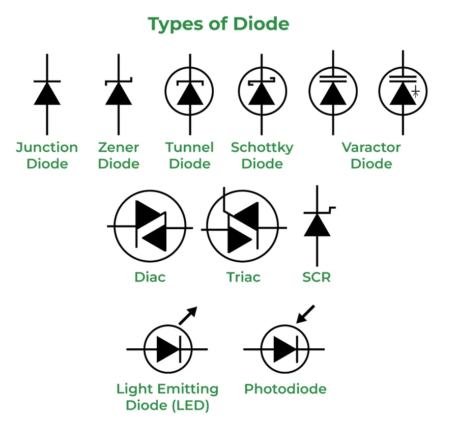
No, the 1N4007 is not a Zener diode. Zener diodes are designed to operate in reverse bias to provide a specific, stable voltage. The 1N4007, on the other hand, is primarily designed for rectification and does not offer reliable voltage regulation in reverse bias. Using it as a Zener diode would not provide the desired performance and could damage the diode. - What are some common alternatives or replacements for the 1N4007 diode?
While the 1N4007 is a common and widely available diode, other diodes can be used as replacements depending on the specific circuit requirements. For lower voltage applications, the 1N4001 (50V) to 1N4006 (800V) series can be used, offering a similar functionality with reduced reverse voltage capability. If you need to switch current more quickly then switching diodes like the 1N4148 or Schottky diodes might be a better choice. For circuits that need higher current or higher voltage diodes in the same through hole package, alternatives such as the 1N5408 (3 Amp/1000V) can be used. - What is the key difference between a 1N4001 and a 1N4007 diode?
The primary difference lies in their peak reverse voltage (PRV) capability. The 1N4001 has a PRV of 50V, whereas the 1N4007 has a PRV of 1000V. They have the same current capabilities with a forward current of 1A. Therefore, if a circuit requires a higher reverse voltage tolerance, a 1N4007 is necessary, while a 1N4001 is sufficient for lower voltage applications. This distinction is very important in circuit design where voltages must be precisely managed. - What are the key specifications to consider when using a 1N4007 diode?
Key specifications to consider include the maximum forward current (1A), which should not be exceeded, the peak reverse voltage (1000V), which determines how much reverse voltage the diode can block before breakdown, and the operating temperature range (-55°C to +150°C), which must be considered under load. These are crucial to ensure that the diode works properly and does not fail prematurely. - How do I identify the anode and cathode of a 1N4007 diode?
The cathode of a 1N4007 diode is typically marked with a silver band. The pin closest to this band is the cathode, and the other pin is the anode. Proper identification is vital because the diode will only conduct current when the anode is more positive than the cathode and if the reverse is true the device does not conduct. Misidentification and improper polarity can damage a circuit and cause improper function. - What are typical applications for the 1N4007 diode?
The 1N4007 diode is used in a wide range of applications, such as in power supplies for rectification, in free-wheeling circuits to protect against inductive kickback from motors and relays, in voltage multiplier circuits and general purpose circuits where the designer wants to allow current flow in one direction only. Its robust characteristics make it suitable for many electronic applications.
Safety Precautions When Working With Diodes and Circuitry
Working with diodes, particularly in electrical circuits, requires strict adherence to safety protocols to prevent personal injury and equipment damage. The 1N4007 diode, while robust for its intended applications, can be compromised by improper handling, excessive voltage, or current. This section details essential safety measures to ensure a safe working environment.
- Electrostatic Discharge (ESD) Precautions
Diodes, like the 1N4007, are susceptible to damage from electrostatic discharge. To prevent ESD damage, always use an antistatic wrist strap when handling these components. Work on an antistatic mat and store the diodes in conductive packaging when not in use. This minimizes the risk of sudden, high-voltage discharges that can compromise the diode's internal structure. - Voltage and Current Limits
Exceeding the diode's rated voltage or current can lead to irreversible damage, potentially causing the diode to short circuit or open. Always operate the 1N4007 within its specified maximum forward current (1A) and peak reverse voltage (1000V). Consult the datasheet and ensure that your circuit design does not exceed these limitations. Pay particular attention to transient voltage spikes, which can occur during inductive load switching or other unexpected events. If necessary, use additional protection circuitry to mitigate transient overvoltages. - Thermal Management
The 1N4007, like all semiconductor devices, generates heat when current passes through it. Excessive heat can degrade the diode's performance and lifespan, potentially causing catastrophic failure. Ensure adequate ventilation and use heat sinks when operating the diode at higher current levels. Monitor the diode's temperature to ensure it remains within its specified operating temperature range. High temperature can cause an increase in reverse leakage current which may impact circuit function. - Proper Polarity and Orientation
Diodes are polarized devices, meaning they only allow current to flow in one direction. Incorrect installation of the 1N4007 can result in circuit malfunction or diode failure. Pay careful attention to the anode and cathode markings on the diode body to ensure proper orientation within the circuit. Confirm the polarity using a multimeter if necessary before powering up the circuit. - Circuit Isolation and Testing
Prior to any circuit modification or testing involving the 1N4007 diode, ensure that the circuit is de-energized. Use insulated tools when probing and testing live circuits to prevent accidental shorts or shocks. Always verify circuit integrity with a multimeter and be mindful of stored energy in capacitors. Working on high voltage circuits require extreme caution and adherence to specific electrical safety procedures.
In the world of electronics, the 1N4007 diode is an indispensable workhorse. Its simplicity and efficiency in rectifying current, combined with its robust specifications and wide range of uses, underscore its importance in modern electronic design. Understanding the 1N4007, its characteristics, and how to use it correctly is crucial for anyone working with electronics. This knowledge not only empowers the reader but also highlights the foundational concepts of electronics. It encourages further exploration into component characteristics and circuit design, making the 1N4007 a starting point and a continuous touchpoint in the world of electronics.