Unveiling the 1N4001 Diode: Your Essential Guide to Rectification
In the world of electronics, the 1N4001 diode is a fundamental component, akin to a one-way street for electrical current. This seemingly simple device, often found in power adapters and electronic circuits, is responsible for converting alternating current (AC) to direct current (DC). Like the unsung hero, it plays a key role in many applications we use daily. This article provides a deep dive into the 1N4001 diode, exploring its characteristics, applications, and why it is still a staple in electronics today.
Understanding the Basics of the 1N4001 Diode
The 1N4001 diode is a fundamental semiconductor device, primarily employed as a rectifier in electronic circuits. As a member of the 1N400x family, it is designed to allow electrical current to flow predominantly in one direction, acting as a one-way valve for electrons. This unidirectional conductivity is critical in converting alternating current (AC) to direct current (DC), a process known as rectification, essential for powering most electronic devices.
Physically, the 1N4001 diode is typically constructed from a silicon crystal, doped to create a p-n junction. This junction forms the core of the diode's functionality. It consists of a p-type region (anode) with an excess of holes and an n-type region (cathode) with an excess of electrons. When a positive voltage is applied to the anode relative to the cathode (forward bias), current flows easily. Conversely, when a reverse voltage is applied, the diode blocks current flow, demonstrating its rectifying properties.
Key Specifications and Electrical Characteristics of the 1N4001 Diode
The 1N4001 diode is a fundamental component in electronics, known for its robust performance in rectification applications. Its key specifications define its operational limits and capabilities, making it crucial for engineers to understand these characteristics for effective circuit design and reliable system operation.
| Parameter | 1N4001 Value | Unit |
|---|---|---|
| Maximum Repetitive Peak Reverse Voltage (VRRM) | 50 | V |
| Maximum RMS Reverse Voltage (VRMS) | 35 | V |
| Maximum DC Blocking Voltage (VDC) | 50 | V |
| Maximum Average Forward Rectified Current (IF(AV)) | 1.0 | A |
| Peak Forward Surge Current (IFSM) (8.3ms Pulse) | 30 | A |
| Typical Forward Voltage Drop (VF) @ 1A | 0.93 | V |
| Maximum Forward Voltage Drop (VF) @ 1A | 1.1 | V |
| Typical Reverse Current (IR) @ VR | 5 | µA |
| Maximum Reverse Current (IR) @ VR | 50 | µA |
| Operating Junction Temperature Range (TJ) | -65 to +175 | °C |
| Storage Temperature Range (TSTG) | -65 to +175 | °C |
It is important to note that the forward voltage drop (VF) of a diode is not a constant value; it varies based on the current flowing through the diode and the operating temperature, with higher currents typically yielding a slightly higher VF. The specifications presented in the table are generally measured at 25°C, so designers should account for changes in VF at higher operating temperatures.
Understanding the reverse current (IR) and how it varies with temperature is essential. As temperature rises, the reverse leakage current increases, potentially affecting the diode's performance in blocking current flow in the reverse direction. It's crucial to consider the temperature-dependent characteristics of the 1N4001, particularly in applications where the diode will operate in elevated temperatures.
| Characteristic | 1N4001 | 1N4002 | 1N4003 | 1N4004 | 1N4005 | 1N4006 | 1N4007 |
|---|---|---|---|---|---|---|---|
| Max. Reverse Voltage (VRRM) | 50V | 100V | 200V | 400V | 600V | 800V | 1000V |
| Forward Current (IF(AV)) | 1A | 1A | 1A | 1A | 1A | 1A | 1A |
| Typical Forward Voltage Drop (VF) | 0.93V | 0.93V | 0.93V | 0.93V | 0.93V | 0.93V | 0.93V |
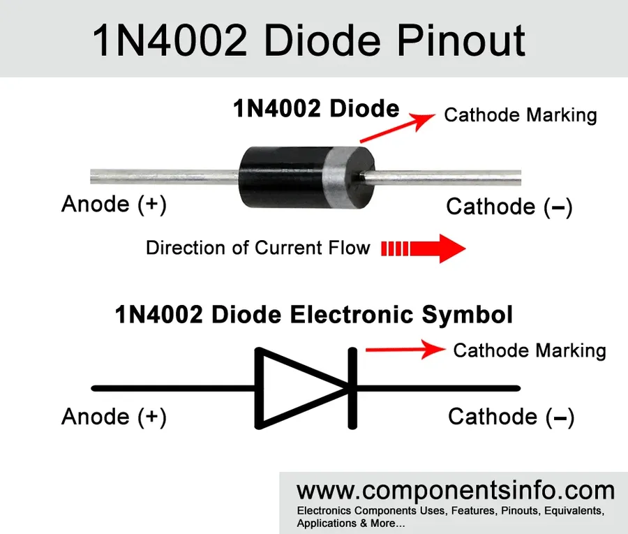
1N4001 Diode Pin Configuration and Identification
Correctly identifying and connecting the pins of a 1N4001 diode is crucial for its proper function within a circuit. The 1N4001 is a two-terminal device, with a distinct anode and cathode that dictate the direction of current flow. Understanding this configuration is fundamental for avoiding circuit malfunction or damage.
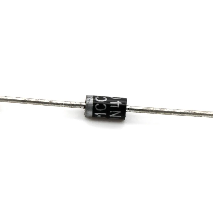
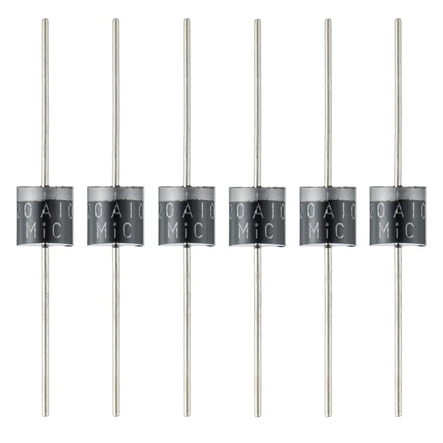
- Physical Appearance
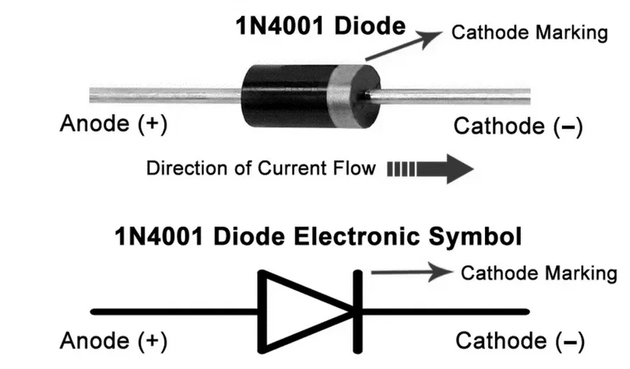
The 1N4001 diode typically has a cylindrical body with a band at one end which is the cathode end. - Cathode Identification
The cathode (-) is marked by a silver or gray band on the diode's body, always the end with the band. This is the terminal where the current flows *out* of the diode in forward bias. - Anode Identification
The anode (+) is the terminal without the band, and the current enters the diode at this end in forward bias. - Pin Connection Best Practices
Always double-check the markings on the diode before soldering or connecting it in a circuit. Incorrect connection will prevent the diode from working correctly. - Circuit Diagram Symbol
The standard schematic symbol for a diode features a triangle pointing to a line. The line represents the cathode, and the tip of the triangle represents the anode.
Real-World Applications of the 1N4001 Diode
The 1N4001 diode, a fundamental component in electronics, excels as a rectifier, adept at converting alternating current (AC) to direct current (DC). Its straightforward functionality and reliability make it ubiquitous in various applications, spanning from everyday power supplies to intricate circuit protection.
Here are some key areas where 1N4001 diodes are commonly employed:
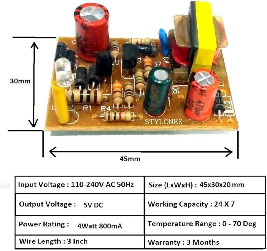
- AC-to-DC Power Supplies (Adapters)
In power adapters for mobile phones, laptops, and other electronic devices, the 1N4001 diode acts as a crucial rectifier. It converts the AC mains voltage to a DC voltage suitable for charging batteries or powering electronic circuits. A bridge rectifier configuration, often using four 1N4001 diodes, is standard, efficiently processing both positive and negative AC cycles to produce a unidirectional DC output. - Voltage Rectification
The primary role of the 1N4001 is rectifying AC signals. This means allowing current to flow in one direction only, thereby 'converting' the alternating current to direct current. This function is indispensable in circuits that require a consistent DC supply. The diode effectively blocks current flow during the reverse cycle of the AC signal, ensuring the circuit receives only the desired DC component. - Freewheeling Diode Protection
When switching inductive loads like relays or motors, a phenomenon known as back EMF (electromotive force) or flyback voltage occurs when the power is disconnected. This sudden voltage surge can damage sensitive circuitry. The 1N4001 diode placed in parallel with the inductive load, acts as a freewheeling diode, providing a path for the current to dissipate, protecting the circuit by shorting the induced voltage transient. - Signal Processing
Though not its primary application, the 1N4001 can be used in basic signal processing circuits. For instance, it can be used as a half-wave rectifier, removing one half of an AC signal. It is also employed in simple clamping circuits, used to limit a signal to a specific voltage level. Its non-linear current-voltage characteristic is exploited to achieve specific signal modifications.
These applications showcase the 1N4001 diode's versatility and essential role in many electronic circuits. Its ability to rectify AC signals, protect circuits from inductive spikes, and manipulate voltage levels is why it remains a cornerstone in electronic design. The 1N4001's characteristics allow for its efficient use, with due consideration of its voltage and current limits. When designing circuits, understanding the 1N4001 diode's behavior and limits is essential for optimal circuit performance and longevity.
1N4001 Diode vs. Other Rectifier Diodes
While the 1N4001 diode serves as a reliable rectifier for many applications, it's essential to understand its limitations and how it compares to other diodes, particularly the 1N4007. The primary difference lies in their reverse voltage capabilities, impacting their suitability for different power supply designs and other rectification needs. This section will detail these distinctions.
| Characteristic | 1N4001 Diode | 1N4007 Diode |
|---|---|---|
| Maximum Repetitive Reverse Voltage (VRRM) | 50V | 1000V |
| Maximum Average Forward Rectified Current (IF(AV)) | 1A | 1A |
| Forward Voltage Drop (VF) (Typical @ 1A) | ~0.7V to 1.1V | ~0.7V to 1.1V |
| Maximum Forward Surge Current (IFSM) | 30A | 30A |
| Operating Temperature Range | -65°C to +175°C | -65°C to +175°C |
| Typical Applications | Low-voltage power supplies, signal rectification | High-voltage power supplies, general purpose rectification |
As shown in the table, both diodes share similar current handling capabilities and forward voltage characteristics. The critical distinction lies in the reverse voltage rating. The 1N4001, with its 50V rating, is suitable for lower voltage applications, whereas the 1N4007, with a significantly higher 1000V rating, can withstand much larger reverse voltages. Therefore, the 1N4007 is favored in applications where there's a potential for higher reverse voltage transients or larger AC input voltages. The similar forward current rating also allows the 1N4007 to be a general purpose alternative to the 1N4001, if voltage is a consideration.
Selecting the Right Diode: When to Use a 1N4001
Choosing the appropriate diode for a circuit is crucial for its reliable operation. The 1N4001 diode is well-suited for general-purpose rectification tasks where its voltage and current ratings align with the circuit's demands. Understanding these parameters is key to selecting the right diode, ensuring both optimal performance and circuit longevity.
Key considerations when selecting the 1N4001 include the circuit's maximum reverse voltage, the expected forward current, and the operating temperature range. For optimal results, the 1N4001's specifications should comfortably exceed the maximum operating parameters of the circuit, to avoid overstressing the diode.
| Parameter | 1N4001 Specification | Considerations for Selection |
|---|---|---|
| Maximum Reverse Voltage | 50V | The peak inverse voltage (PIV) the diode will encounter must be less than 50V. |
| Forward Current | 1A | The continuous forward current the diode will conduct must be less than 1A. |
| Forward Voltage Drop | Approximately 0.7-1.1V | Consider the voltage drop when the diode is conducting to ensure the proper operation of the circuit. |
| Operating Temperature Range | -65°C to +175°C | Ensure the expected operating temperature of the circuit falls within the specified limits of the diode. |
Practical Tip: When dealing with AC-to-DC power supplies, ensure that the peak inverse voltage of the AC signal is accounted for, not just the RMS voltage. For example, a circuit using 36 VAC will reach close to 50.9V peak, meaning that the circuit is very close to the limit of the diode's capabilities
If the circuit's voltage or current demands exceed the 1N4001's ratings, consider using a diode with higher specifications, such as the 1N4007. The 1N4007 diode has a higher peak reverse voltage rating, which makes it more suitable for applications requiring higher voltage capabilities. The selection of the appropriate diode is essential to preventing diode failure and circuit malfunction.
Frequently Asked Questions About the 1N4001 Diode
This section addresses common questions regarding the 1N4001 diode, offering precise answers to aid in your understanding and practical application of this fundamental electronic component. We delve into its usage, comparisons with other diodes, current handling, and voltage characteristics.
- What are the primary applications of a 1N4001 diode?
The 1N4001 diode is primarily used for rectification, converting AC power to DC. It's widely found in power adapters, battery chargers, and various circuits requiring unidirectional current flow. It also functions as a freewheeling diode in inductive load circuits and as a general-purpose signal diode. - What differentiates the 1N4001 from the 1N4007 diode?
The key difference lies in their reverse voltage ratings. The 1N4001 has a maximum reverse voltage of 50V, while the 1N4007 can withstand up to 1000V. Both diodes have similar forward current capabilities (1A), but the 1N4007 is chosen for higher voltage applications where a larger safety margin is required to prevent reverse breakdown. Therefore the 1N4007 diode has a larger margin for safety when handling high voltage. - What is the maximum current the 1N4001 diode can handle?
The 1N4001 diode is rated for a maximum forward current of 1 Ampere (1A). Exceeding this limit can cause overheating and damage to the diode. Careful design and heat dissipation considerations are necessary when the diode operates near its rated current. - What is the typical forward voltage drop across a 1N4001 diode?
When conducting current in the forward direction, the 1N4001 diode exhibits a typical voltage drop of approximately 0.7V. This voltage drop is relatively constant over a wide range of forward current values and is inherent to silicon-based diodes. It must be considered in circuit designs, specifically when determining the operating voltage of a circuit. - Can a 1N4001 diode be used to protect a circuit against reverse polarity?
Yes, the 1N4001 can be used for reverse polarity protection. When connected in series with the power supply, the diode will conduct in the correct polarity and block current flow when the polarity is reversed, thus preventing damage to the protected circuit, however, it's important to note that the diode itself needs to withstand the peak current during a reverse polarity situation. The reverse breakdown voltage must also be respected. - What is the safe operating temperature range for a 1N4001 diode?
The 1N4001 diode has a standard operating temperature range typically from -65°C to +175°C. However, exceeding these temperatures can compromise the diode's performance and lifespan. It is critical to consider ambient temperature, heat dissipation measures and junction temperature during circuit design to ensure reliable performance. - Is the 1N4001 diode suitable for high-frequency applications?
The 1N4001 is primarily a rectifier diode designed for use in AC line frequencies (50/60 Hz) and is not optimized for high-frequency applications. At higher frequencies, the diode's junction capacitance and reverse recovery time become significant, leading to losses and inefficiency. Schottky diodes are more suited for high-frequency switching applications.
Troubleshooting and Common Issues with 1N4001 Diodes
The 1N4001 diode, while robust for its intended applications, can encounter issues if not operated within its specified parameters or if subjected to certain environmental conditions. Understanding common failure modes and implementing preventative measures is critical for reliable circuit performance.
- Overheating
Excessive current flow beyond the 1A forward current rating or inadequate heat dissipation can lead to overheating. This can result in performance degradation, reduced lifespan, or catastrophic failure of the diode. Verify proper heat sinking if the diode is handling significant power, and ensure the circuit is designed to stay within the diode's rated current. - Reverse Leakage Current
While diodes are intended to block current in the reverse direction, a small leakage current will always be present. Excessive reverse voltage approaching or exceeding the 50V maximum rating can cause the leakage current to increase substantially and potentially damage the diode. Always operate within the specified reverse voltage limit. - Forward Voltage Drop Issues
An unexpected increase in the forward voltage drop can indicate diode degradation. This increased voltage drop can cause the circuit to function incorrectly. Regularly check the forward voltage drop under load to verify the health of the diode. If there are large changes, replace the diode. - Open or Short Circuit Failures
Diodes can fail in either an open or short-circuit configuration. An open circuit failure will prevent the diode from conducting, while a short circuit failure will allow current flow in both directions. The use of a diode tester or multimeter is essential to diagnose these failure modes accurately. - Mechanical Stress
Physical stress, such as excessive bending of the leads, can damage the internal structure of the diode, causing premature failure. Ensure leads are properly supported and not subjected to excessive mechanical forces during mounting and operation. - Transient Voltage Spikes
Transient voltage spikes can occur due to switching events or external factors, which can exceed the reverse voltage tolerance of the 1N4001. Implement transient voltage suppression techniques, such as using TVS diodes or MOVs, to protect the 1N4001.
The 1N4001 diode stands as a cornerstone of electronics, reliably performing the crucial task of rectification. From basic power supplies to complex circuits, its consistent performance makes it a go-to component. Whether you are a hobbyist or a professional, understanding the 1N4001, its specifications and applications, is essential. As technology advances, remember the vital role this component plays and, with that, the knowledge you gained from this article, enhancing your understanding of electronic engineering. The 1N4001 diode continues to demonstrate that sometimes the simplest solutions are the most effective.