Unveiling the Power of SS14 Diode: A Comprehensive Guide
From everyday electronics to complex industrial machinery, diodes play a crucial role. Among them, the SS14 diode stands out for its efficiency as a Schottky rectifier. This article will delve into the intricacies of the SS14, exploring its working principles, applications, and what makes it a cornerstone component in modern circuits, bridging the gap between fundamental technology and its practical applications.
Understanding the SS14 Schottky Diode
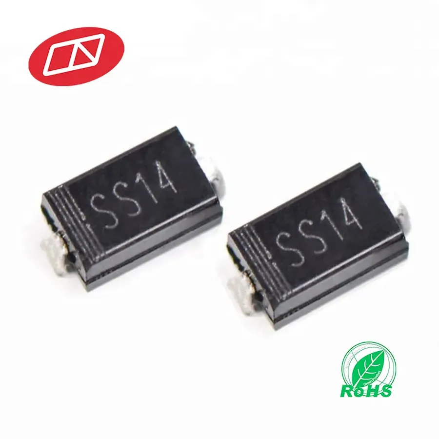
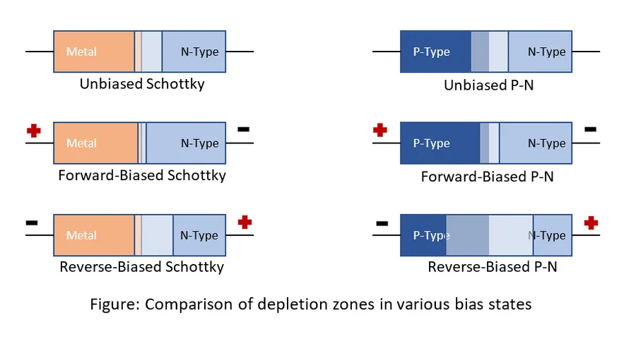
The SS14 is a surface-mount Schottky Barrier Rectifier diode, characterized by its low forward voltage drop and rapid switching speed. These attributes make it highly efficient in various electronic applications. It leverages a metal-semiconductor junction, rather than a traditional p-n junction, facilitating its low forward voltage drop compared to traditional diodes. The SS14 diode is typically constructed using a metal-semiconductor junction, such as a metal (like aluminum) in contact with an N-type semiconductor (typically silicon). When a forward voltage is applied, electrons from the semiconductor can readily flow into the metal, while the Schottky barrier prevents the reverse current flow.
SS14 Diode Specifications and Parameters
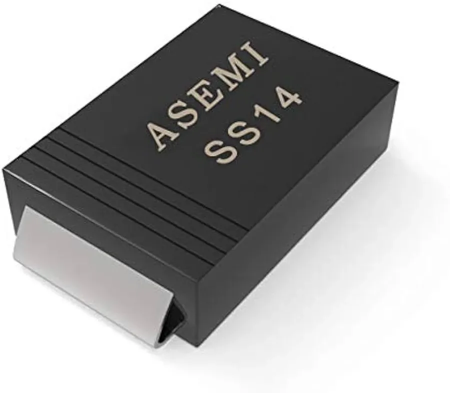
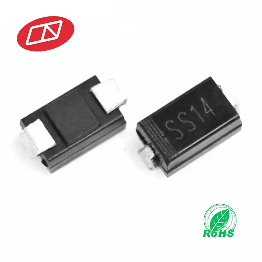
The SS14 Schottky diode is characterized by specific electrical parameters crucial for circuit design and performance. These parameters include forward voltage drop, reverse voltage, current rating, and its physical packaging, typically an SMA/DO-214AC surface-mount package. Understanding these specifications is essential for proper application of the SS14 diode.
| Parameter | Typical Value | Unit | Description |
|---|---|---|---|
| Maximum Repetitive Peak Reverse Voltage | 40 | V | The maximum voltage that can be applied in reverse periodically without causing breakdown. |
| Maximum Average Forward Rectified Current | 1.0 | A | The maximum current the diode can handle continuously in the forward direction. |
| Maximum Peak Forward Surge Current | 40 | A | The maximum current the diode can withstand for a short period (typically one cycle). |
| Forward Voltage Drop (at 1A) | 0.55 | V | The voltage drop across the diode when a forward current of 1A is flowing. Note that it will vary depending on the forward current. |
| Operating Junction Temperature | -55 to +125 | °C | The range of temperatures in which the device will operate properly. |
| Package Type | SMA (DO-214AC) | - | The physical package of the diode, surface mount. |
It is important to note that these values can slightly vary between manufacturers. Therefore, always consult the specific datasheet from the chosen vendor for precise parameter values. The typical forward voltage drop is around 0.55 V at 1A, a crucial characteristic contributing to its high efficiency as a rectifier or in other applications.
Key Features of the SS14 Diode
The SS14 Schottky diode distinguishes itself through a combination of performance-enhancing attributes, making it a preferred component in various electronic applications. Its key features, including low forward voltage drop, high efficiency, minimal power losses, over-voltage protection capabilities, and suitability for automated assembly processes, underscore its value in modern circuit designs.
- Low Forward Voltage Drop
The SS14 exhibits a significantly low forward voltage drop, typically around 0.5V or less at its rated current. This characteristic minimizes power dissipation and enhances overall circuit efficiency. This reduction in voltage drop is critical for energy-efficient designs, especially in battery-powered and portable devices. - High Efficiency
Due to the low forward voltage drop, the SS14 diode operates with high efficiency. This efficiency translates to less heat generation during operation, which is crucial for maintaining the reliability and longevity of electronic circuits. Higher efficiency reduces energy waste. - Low Power Losses
The reduced forward voltage drop directly contributes to minimized power losses within the circuit. This is advantageous in power management applications and helps in achieving better energy utilization, especially in high-frequency operations. Lower power losses also mean less demand on cooling systems. - Over-Voltage Protection
Schottky diodes, including the SS14, offer over-voltage protection by quickly conducting current when a reverse voltage exceeds its specified limit. This rapid response helps in safeguarding sensitive components downstream, preventing damage from voltage spikes and transient events. This protective feature is vital for maintaining circuit integrity. - Ideal for Automated Placement
The SS14 diode is commonly packaged in an SMA/DO-214AC surface-mount package, making it highly suitable for automated pick-and-place assembly lines. This ensures high-speed, accurate placement on printed circuit boards (PCBs) during mass production. Its standardized package significantly streamlines manufacturing processes.
Applications of the SS14 Rectifier Diode
The SS14 Schottky diode's unique characteristics, notably its low forward voltage drop and high switching speed, make it a versatile component across numerous electronic applications. Its efficiency in minimizing power loss and its rapid response to changing current demands are critical in many circuits. This section details several key application areas where the SS14 diode is commonly utilized.
- Power Inverters
In power inverters, the SS14 diode acts as a freewheeling diode, handling the inductive kickback when switching devices turn off. This protection prevents voltage spikes and ensures the efficient and reliable operation of the inverter. Its ability to handle high frequencies without significant power loss makes it suitable for modern high-efficiency inverters. - Freewheeling Circuits
The SS14 is commonly found in freewheeling circuits, also known as flyback circuits. These circuits are used to provide a path for current when an inductive load is suddenly de-energized. The low forward voltage drop of the SS14 is crucial here, as it minimizes energy loss during the flyback process, thus improving overall circuit efficiency and reducing heat generation. This is applicable in motor control circuits and power supplies. - Polarity Protection
The SS14 provides effective polarity protection in circuits. By being reverse biased in normal operation, it prevents damage from an accidental reverse polarity connection. When reverse polarity occurs, the diode conducts, creating a short circuit and preventing damage to sensitive components. It's commonly used in battery-powered devices to protect the electronics from incorrect battery insertion. - High-Frequency Switching Circuits
Given its fast switching capabilities, the SS14 excels in high-frequency applications such as SMPS (Switch Mode Power Supplies) and high-frequency DC-DC converters. The rapid response and low forward voltage drop minimize switching losses, contributing to higher efficiency and reduced heat dissipation in power conversion. It’s commonly used in fast charging adapters. - Specific Device Examples
The SS14 can be found in devices like USB chargers, laptops power supplies, solar panel circuits, LED lighting drivers, and various portable electronic devices where its efficiency and size is a necessity.
SS14 vs. Other Schottky Diodes: Comparative Analysis
The SS14 Schottky diode stands out for its specific performance characteristics, but understanding how it compares to other Schottky diodes is crucial for optimal circuit design. This section provides a comparative analysis of the SS14 with similar diodes, including the SS12, SS13, SS16, and 1N5819, highlighting key differences in their electrical parameters. We will also address the common confusion between the SS14 and SS34 diodes.
| Parameter | SS12 | SS13 | SS14 | SS16 | 1N5819 |
|---|---|---|---|---|---|
| Maximum Average Forward Current (A) | 1.0 | 1.0 | 1.0 | 1.0 | 1.0 |
| Maximum Peak Reverse Voltage (V) | 20 | 30 | 40 | 60 | 40 |
| Typical Forward Voltage Drop (V) at 1A | 0.38 - 0.55 | 0.4 - 0.58 | 0.45 - 0.6 | 0.47 - 0.65 | 0.45 - 0.6 |
| Package Type | SMA/DO-214AC | SMA/DO-214AC | SMA/DO-214AC | SMA/DO-214AC | DO-41 |
The table above illustrates that while all these diodes are in the 1A current range, their key difference lies in the reverse voltage capabilities. For example, the SS12 has the lowest reverse voltage rating at 20V, making it suitable for lower-voltage applications, while SS16 can handle up to 60V, suited for more demanding voltage requirements. The forward voltage drop varies slightly among these diodes, which is an important consideration for power efficiency in switching applications. Additionally, the 1N5819, while similar in voltage and current ratings, comes in a different package (DO-41) which can influence physical integration in designs.
A common point of confusion arises between the SS14 and SS34 diodes. While both are Schottky diodes with similar physical packages (SMA/DO-214AC), their main difference is in their maximum reverse voltage rating. The SS14 has a maximum reverse voltage rating of 40V, whereas the SS34 is rated for 30V. This difference is a critical factor when selecting a diode based on specific voltage requirements of the circuit. Users need to check the manufacturer datasheet for exact values to ensure they select the right component for the intended application.
SS14 Diode Testing and Troubleshooting
Testing an SS14 Schottky diode is crucial to ensure its proper functionality within a circuit. This section provides a practical guide on how to use a multimeter for testing and outlines basic troubleshooting steps when issues arise.
Before testing an SS14 diode, it's imperative to understand that Schottky diodes, including the SS14, exhibit a lower forward voltage drop than standard silicon diodes. This characteristic is key to interpreting test results accurately. Moreover, diodes should ideally be tested out of circuit to avoid interference from other components. However, in-circuit testing can still provide valuable diagnostic information with some caveats.
Always observe safety precautions when working with electronic circuits, especially when using a multimeter to avoid short circuits and potential damage to the device under test or measuring equipment.
- Testing the SS14 Diode Out of Circuit
Set your multimeter to diode test mode. If your multimeter does not have a dedicated diode test mode, you can use the resistance setting, but the results will be less conclusive. Connect the red probe (positive) to the anode side of the diode (typically the side without the band) and the black probe (negative) to the cathode (the side with the band). In this forward-biased state, the multimeter should display a voltage drop, typically in the range of 0.2V to 0.5V for a Schottky diode like the SS14. Reverse the probes, connecting the red probe to the cathode and black to the anode, the multimeter should display 'OL' or '1', indicating very high or infinite resistance, demonstrating the diode's blocking behavior in the reverse direction. - Interpreting the Results
A low forward voltage drop (e.g., 0.2V to 0.5V) in the forward direction and 'OL' or '1' in the reverse direction indicates that the diode is functioning correctly. A reading of 0V in both directions suggests a shorted diode, while an 'OL' or '1' reading in both directions usually indicates an open diode. A high forward voltage drop or low reverse resistance indicates a defective diode. - In-Circuit Testing
When testing the SS14 diode in circuit, the readings may be affected by other components. The forward voltage drop might appear lower, and the reverse resistance reading may be smaller than what's expected. If a diode failure is suspected but the readings are inconclusive, always remove the component and test it out of circuit for a more accurate assessment. - Basic Troubleshooting Steps
If a diode is suspected of being faulty based on initial measurements, confirm by performing out-of-circuit test as described above. For issues like overheating and burnout, check if the current is within the SS14's specified limits (typically 1A). If the circuit is experiencing unusual behavior, inspect the connections and nearby components and look for solder issues and signs of physical damage, such as cracks or discoloration. Always refer to the datasheet for specific parameters and verify your readings with those specified by the manufacturer.
Finding SS14 Diode Equivalents and Replacements
Selecting an appropriate equivalent or replacement for the SS14 Schottky diode requires careful consideration of its key electrical parameters and physical package. This ensures seamless integration into existing circuits and maintains the desired performance characteristics. Critical parameters include forward voltage drop (Vf), reverse voltage (Vr), forward current (If), and the physical package (SMA/DO-214AC).
A suitable replacement for the SS14 diode must match or exceed its specifications. For instance, a higher current rating (If) can be used, but a lower one should not, as it may lead to component failure. Similarly, the reverse voltage (Vr) rating of the replacement must be equal to or greater than that of the SS14 to avoid breakdown under reverse bias conditions. The forward voltage drop (Vf) should ideally be equal to or lower than the SS14 for efficiency. The package should match to fit into the existing PCB footprint.
When searching for equivalents, it is crucial to consult datasheets from different manufacturers to identify components with comparable specifications. It is also important to consider the operating environment (temperature, humidity, etc.) as it can affect the performance and reliability of the replacement component.
| Parameter | SS14 | Equivalent Considerations |
|---|---|---|
| Forward Voltage Drop (Vf) | ~0.5V (at 1A) | Equal to or lower |
| Reverse Voltage (Vr) | 40V | Equal to or higher |
| Forward Current (If) | 1A | Equal to or higher |
| Package Type | SMA/DO-214AC | Must match |
Common equivalents can be found among other Schottky diodes within the same series from various manufacturers. For example, an SS16, which has a similar package and a slightly higher reverse voltage and current rating, could be considered if a safety margin is needed. Components from brands like Vishay, ON Semiconductor, and Diodes Incorporated offer potential SS14 alternatives.
Frequently Asked Questions About the SS14 Diode
This section addresses common queries about the SS14 diode, offering concise answers to enhance understanding of its functionality and applications. These FAQs are designed to provide quick and clear information regarding the SS14 diode and its related topics.
- What exactly is an SS14 diode?
The SS14 is a Schottky diode, characterized by its low forward voltage drop and fast switching speed. It's primarily used for rectification and protection in electronic circuits. - What are the typical applications for an SS14 diode?
The SS14 is commonly utilized in power inverters, freewheeling circuits, polarity protection, and high-frequency switching applications due to its efficiency in handling fast switching tasks. - What does 'Schottky' mean in reference to the SS14 diode?
A Schottky diode, such as the SS14, is a semiconductor diode formed with a metal-semiconductor junction, as opposed to the traditional semiconductor-semiconductor junction. This construction provides it with a lower forward voltage drop and faster switching speeds compared to typical diodes. - What are common equivalents for the SS14 diode?
While the SS14 is widely used, other diodes such as the SS12, SS13 and SS16 can be suitable substitutes, provided that their voltage, current, and package specifications match the requirements of the circuit. - What is the difference between the SS14 and SS34 diodes?
The primary distinction lies in their current ratings: the SS14 has a 1A rating, while the SS34 handles 3A. Both are Schottky diodes, but the SS34 is chosen when higher current handling capability is necessary. - How can I test an SS14 diode using a multimeter?
To test an SS14 diode with a multimeter, switch to the diode test mode. A typical reading will show a forward voltage drop (around 0.2-0.5V) when the probes are correctly aligned (anode with the red probe, cathode with the black probe). A very low or very high reading, or no reading at all indicates a failure in the diode. - How does the low forward voltage drop of the SS14 diode benefit circuits?
The SS14's low forward voltage drop reduces power loss and heat generation, which increases efficiency and extends the life of the circuit, making it suitable for battery powered applications.
In conclusion, the SS14 diode is a highly efficient and versatile component essential in modern electronics, specifically as a Schottky rectifier. With its low forward voltage drop, high current capacity, and overvoltage protection, the SS14 diode exemplifies the progress in semiconductor technology. Whether you are designing a new circuit or troubleshooting an existing one, understanding the functionality of the SS14 diode and its equivalents is crucial. As technology advances, the SS14 and its derivatives will continue to power innovation across many electronic applications.