Unveiling the Power of the 2N2222 NPN Transistor: A Comprehensive Guide
Imagine a tiny switch controlling a flow of electricity, much like a gate in a canal system. That's essentially what the 2N2222 NPN transistor does, but at an electronic level. This ubiquitous component, a workhorse in countless circuits, is a crucial part of modern electronics, from simple toys to complex industrial machinery. We will dive deep into this powerful little device, exploring its inner workings, uses, and why the 2N2222 NPN transistor is a staple in the world of electronics.
Understanding the 2N2222 NPN Transistor
The 2N2222 is a ubiquitous NPN bipolar junction transistor (BJT) renowned for its versatility as both a current-controlled switch and an amplifier. At its core, the 2N2222 is a three-terminal semiconductor device featuring a collector, a base, and an emitter, each playing a crucial role in its operation.
An NPN transistor is constructed from three semiconductor layers. The 'N' regions represent material doped with impurities that provide a surplus of electrons (negative charge carriers), these are the collector and the emitter. The 'P' region, the base, is doped with impurities that have a deficiency of electrons (positive charge carriers). The flow of current is controlled by the base, a small current at the base can control a large current flowing from the collector to the emitter, enabling its dual function as a switch and an amplifier.
2N2222 Pinout and Configuration

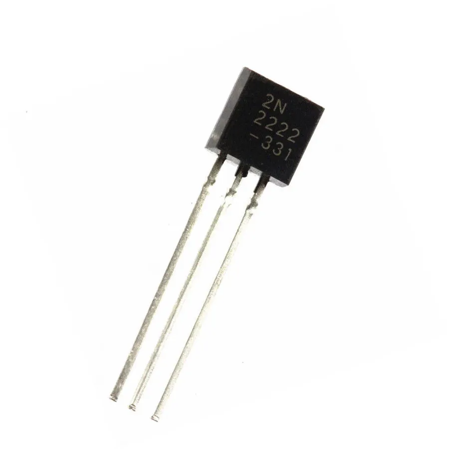
The 2N2222 NPN transistor, commonly housed in a TO-92 package, features three terminals: the emitter, the base, and the collector. Correctly identifying these pins is crucial for the proper operation of any circuit utilizing this transistor. Incorrect pin assignment can lead to circuit malfunction or even damage to the transistor or other components.
- Emitter (E)
The emitter pin is typically the one on the left when viewing the flat side of the TO-92 package with the leads pointing down. It is the terminal from which current flows out of the transistor in normal operation. - Base (B)
The base pin is located in the center of the TO-92 package. A small current applied to the base controls the larger current flow between the collector and emitter. - Collector (C)
The collector pin is located on the right of the TO-92 package. Current flows into the collector terminal from the power source. It is the main current carrying terminal in transistor operation.
It is critical to always confirm the pinout of the 2N2222 before connecting it into a circuit. Datasheets from the manufacturer are the most reliable source of pinout information. Variations in packages from different manufacturers are extremely rare but always should be checked.
Key Electrical Characteristics of the 2N2222
Understanding the electrical characteristics of the 2N2222 NPN transistor is crucial for effective circuit design and application. These parameters define the transistor's operational limits and capabilities, ensuring it functions as intended within a circuit. Key characteristics include current gain (hFE), collector current (Ic), collector-emitter voltage (VCE), and power dissipation, each playing a vital role in determining the transistor's performance.
| Parameter | Symbol | Typical Value | Unit | Description |
|---|---|---|---|---|
| Current Gain | hFE | 100-300 | - | Ratio of collector current to base current, indicating amplification capability; Varies with collector current and temperature. |
| Collector Current | Ic | 800 | mA | Maximum continuous current that can flow through the collector; exceeding can damage the transistor. |
| Peak Collector Current | Ic(peak) | 1 | A | Maximum peak current the collector can handle for a short duration. |
| Collector-Emitter Voltage | VCE | 40 | V | Maximum voltage that can be applied between the collector and emitter; exceeding can lead to breakdown. |
| Collector-Base Voltage | VCB | 75 | V | Maximum voltage that can be applied between the collector and base; exceeding can lead to breakdown. |
| Emitter-Base Voltage | VEB | 6 | V | Maximum voltage that can be applied between the emitter and base; exceeding can lead to breakdown. |
| Power Dissipation | Pd | 0.5 | W | Maximum power the transistor can safely dissipate as heat; exceeding can cause overheating and failure. (TA = 25°C) |
| Operating Temperature | Tj | -55 to +150 | °C | The range within which the transistor can operate without damage. |
Applications of the 2N2222 NPN Transistor
The 2N2222 NPN transistor's versatility makes it a staple in numerous electronic applications, functioning effectively as both a switch and an amplifier. Its cost-effectiveness, combined with its robust performance, contributes to its widespread use in various electronic designs, from basic hobby circuits to more complex industrial systems.
- Switching Circuits
The 2N2222 is frequently employed as an electronic switch. In such applications, a small current at the base of the transistor controls a larger current flow between the collector and emitter, enabling the switching of loads like LEDs, relays, or other circuit components. - Amplifier Circuits
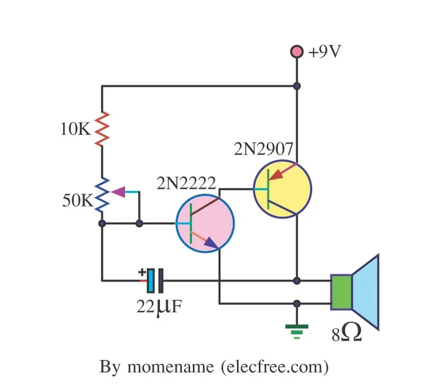
Utilizing its current gain characteristics (hFE), the 2N2222 can amplify weak electrical signals. Common applications include small-signal amplification in audio pre-amplifiers and other signal conditioning circuits. - Relay Drivers
Due to its current handling capability, the 2N2222 is commonly used to drive electromechanical relays. A microcontroller or logic circuit can control the base current, allowing the relay to switch a separate, higher-power circuit. - Oscillator Circuits
The 2N2222 is used in oscillator circuits for generating various types of signals. These signals can be used as clock signals or for different types of sensors and communication applications. - Low-Power Inverters
The 2N2222 can be used in inverters to convert DC power to AC power. By using a series of transistors in a push-pull configuration, the DC signal can be converted to an AC signal. However, these inverters are typically low-power.
2N2222 as a Switch
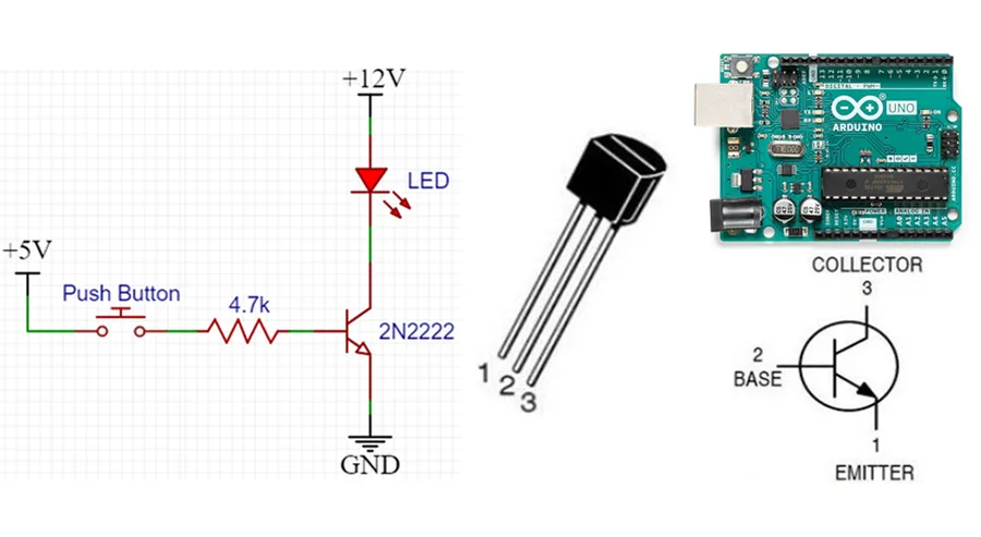
The 2N2222 NPN transistor excels as an electronic switch, leveraging its ability to control current flow between the collector and emitter terminals by manipulating the base current. This characteristic allows the 2N2222 to effectively turn on or off devices or circuits with a small control signal.
In a switching configuration, the 2N2222 operates in two primary states: 'cutoff' and 'saturation'. When no current is applied to the base, the transistor is in cutoff, preventing current flow between the collector and emitter. Conversely, when sufficient base current is provided, the transistor enters saturation, allowing maximum current flow from collector to emitter, effectively closing the switch. This on/off characteristic makes it useful in a variety of switching applications.
- Base Current Control
The base current (Ib) directly controls the collector current (Ic). To switch the 2N2222 'on', a small current must be supplied to the base. This is usually achieved through a resistor connected to a control voltage. - Saturation Region
When the base current is sufficient, the transistor operates in its saturation region. In this state, the collector-emitter voltage (VCE) is minimal (ideally 0V), and the transistor is 'on', allowing maximum current flow. - Cutoff Region
When no base current is applied (or the base voltage is below the threshold), the transistor operates in its cutoff region. In this state, there is essentially no current flow between the collector and emitter (Ic ≈ 0), and the transistor is 'off'.
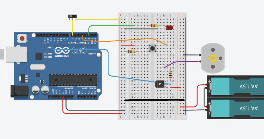
A common example is using the 2N2222 to switch an LED. The collector is connected to the LED and a current-limiting resistor, which then connects to a power source. The base is connected through another resistor to a digital output, such as a microcontroller pin. When the microcontroller outputs a high signal, current flows into the base, and the transistor saturates, turning the LED on. When the output is low, the transistor is in cutoff, and the LED is off. This simple circuit demonstrates the transistor's capability as a controlled electronic switch.
2N2222 as an Amplifier
The 2N2222 NPN transistor, beyond its switching capabilities, excels as a small-signal amplifier, leveraging its inherent current gain (hFE) to boost weak electrical signals. This section details the fundamental principles and applications of the 2N2222 in amplifier circuits.
The transistor's amplification relies on the fact that a small change in the base current can produce a much larger change in the collector current. The ratio of the change in collector current to the change in base current is called the transistor's current gain, or hFE (also known as β).
When configuring a 2N2222 as an amplifier, the transistor is biased in the active region, allowing both forward and reverse current flow. This operational region is critical for linear amplification, where the output signal is a faithful reproduction of the input signal, but at a higher amplitude.
- Common-Emitter Amplifier Configuration
In this configuration, the input signal is applied to the base, and the amplified output signal is taken from the collector. The emitter is common to both the input and output circuits. This is a popular configuration because it provides both voltage and current gain. - Biasing for Linear Operation
For faithful amplification, the transistor needs to be correctly biased, which means that a DC operating point needs to be established. This is typically achieved using a combination of resistors to set the base and collector currents. Proper biasing ensures that the transistor operates in its linear region. - Signal Gain and Frequency Response
The gain of an amplifier is defined as the ratio of the output signal amplitude to the input signal amplitude. The 2N2222's gain (hFE) is frequency dependent, with the gain typically dropping off at higher frequencies. Therefore, for reliable amplification the bandwidth of the amplifier must be considered.
Small signal amplifier circuits using the 2N2222 are foundational for numerous electronic devices and systems, enabling the amplification of weak signals to levels that can be further processed, measured, or used to control other devices.
2N2222 vs. 2N3904: A Comparative Analysis
The 2N2222 and 2N3904 are both ubiquitous NPN bipolar junction transistors, frequently employed in a wide array of electronic circuits. While both serve as fundamental building blocks for amplification and switching, they exhibit key differences in their electrical characteristics that influence their suitability for particular applications. This section provides a comparative analysis, emphasizing their dissimilarities to aid in informed component selection.
| Parameter | 2N2222 | 2N3904 |
|---|---|---|
| Collector Current (Ic) Max | 800 mA | 200 mA |
| Collector-Emitter Voltage (VCE) Max | 40 V | 40 V |
| Power Dissipation (PD) Max | 625 mW | 350 mW |
| Current Gain (hFE) Min | 35 (at 150mA) | 30 (at 10mA) |
| Transition Frequency (fT) | 300 MHz | 300 MHz |
| Package Type | TO-92, TO-18 | TO-92 |
| Typical Application | Medium power switching and amplification | Low power general purpose switching and amplification |
The 2N2222 is generally preferred for applications requiring higher current handling and power dissipation capabilities, while the 2N3904 is more suited for lower power and lower current general-purpose circuits. Although they share the same transition frequency, the current gain (hFE) differs slightly across different current levels. The 2N2222 offers a slightly higher current handling capacity, a difference that should be taken into account when deciding between the two. Both come in the TO-92 package.
Selecting Equivalents and Replacements for the 2N2222
When seeking replacements or equivalents for the 2N2222 NPN transistor, careful consideration of key electrical parameters and intended application is paramount. The 2N2222, a ubiquitous NPN transistor in a TO-92 package, has various suitable alternatives. Understanding the nuances between different transistor variants ensures seamless integration within a circuit.
- Key Considerations for 2N2222 Replacements
When choosing an equivalent, prioritize matching or exceeding the 2N2222’s key specifications: maximum collector current (Ic), collector-emitter voltage (VCE), power dissipation, and current gain (hFE). Ensure the replacement part is an NPN transistor with the correct pinout (Emitter, Base, Collector). - 2N2222A vs 2N2222
The 2N2222A is a common variant that generally offers a higher voltage rating compared to the standard 2N2222. While often interchangeable, review your circuit's voltage requirements. The 2N2222A has the same pinout as the 2N2222. - Common 2N2222 Replacements
Other NPN transistors with similar or enhanced capabilities may be used as replacements, such as the PN2222, 2N3904, and the BC547. Datasheets must be reviewed to ensure compatibility regarding current handling, voltage ratings, and hFE values. - Pinout Verification
Always confirm the pinout of the replacement transistor. Although the TO-92 package typically has a standard pinout, manufacturers may sometimes differ, resulting in circuit failure if incorrectly connected. - Manufacturer's Data Sheets
The first step for choosing a replacement part is to consult the original 2N2222 datasheet and compare it to the potential replacement datasheets. This ensures all critical parameters are met or exceeded and ensures a stable, reliable circuit operation.
Frequently Asked Questions About the 2N2222 NPN Transistor
This section addresses common questions regarding the 2N2222 NPN transistor, offering concise and technically accurate answers to enhance your understanding and practical application of this versatile component.
- Why is the 2N2222 so popular?
The 2N2222's enduring popularity stems from its robust performance, low cost, and broad availability. It is a general-purpose NPN transistor suitable for a wide range of applications, making it a staple in electronics. - What is the difference between the 2N2222 and the 2N2222A?
The primary difference lies in their voltage ratings. The 2N2222A typically has a higher collector-emitter voltage (VCEO) rating than the standard 2N2222, making it more robust in higher voltage applications. Functionally, they are largely interchangeable but ensure your circuit requirements are within the specifications of the chosen part. - Can the 2N2222 be used as a PNP transistor?
No, the 2N2222 is an NPN transistor and cannot function as a PNP transistor. An NPN transistor is current-controlled with a small current at the base causing a larger current to flow between the collector and the emitter, with the current flowing from collector to emitter. PNP transistors are the inverse, they are also current-controlled, but the current flows from emitter to collector. - What is an NPN transistor used for?
NPN transistors like the 2N2222 are primarily used for switching and amplification. They act as current-controlled switches, allowing a small base current to control a larger current between the collector and emitter, making them suitable for applications like driving relays, LEDs, and creating amplifier circuits. - What are some suitable replacements for the 2N2222 transistor?
Common replacements for the 2N2222 include the 2N3904, which is a lower-power alternative, and the PN2222A, which is a functionally equivalent but is often in a surface mount package. When selecting a replacement, consider the required current, voltage ratings, and gain (hFE) of your application. - What are the typical current and voltage limits for the 2N2222?
The 2N2222 typically has a maximum collector current (Ic) of about 800mA and a collector-emitter voltage (VCEO) rating of around 40V. However, these values can vary slightly among manufacturers, so it's always crucial to consult the specific datasheet. - What does hFE mean in a transistor datasheet?
hFE, often referred to as beta (β), represents the transistor's current gain in a common-emitter configuration. It's the ratio of collector current (Ic) to base current (Ib). A higher hFE value means the transistor can amplify current more effectively but does not directly mean that the device will switch more efficiently. The 2N2222's hFE is typically between 100 and 300. This value is usually a range on the datasheet because the hFE will change with varying current.
The 2N2222 NPN transistor, a seemingly simple electronic component, is in fact a pivotal part of a wide range of circuits and devices. From simple switching mechanisms to complex amplification stages, its versatility and cost-effectiveness make it the go-to choice for engineers and hobbyists. Whether it's controlling a light emitting diode or boosting the gain of an audio circuit, a solid understanding of the 2N2222 is foundational in the world of electronics. As technology continues to advance, the role of transistors, especially the 2N2222 npn transistor and its successors, remains as important as ever in shaping our technological future. Understanding this component unlocks a deeper understanding of electronic circuits and their endless applications.