Varistors: Your Ultimate Guide to Surge Protection

In our increasingly tech-dependent world, the silent guardian of our electronic devices often goes unnoticed - the varistor. This unassuming component acts as a vital surge protector, safeguarding sensitive circuits from harmful voltage spikes. Much like a pressure relief valve for electrical circuits, it diverts excess energy and prevents costly damage. In this article, we'll delve into the heart of varistors, exploring their function, applications, testing methods, and why they're essential for your electronic devices.
What is a Varistor?
A varistor, also known as a Voltage Dependent Resistor (VDR), is a crucial two-terminal electronic component exhibiting a non-linear resistance characteristic that changes inversely with applied voltage. This unique property allows it to act as a surge protector by shunting excess current away from sensitive downstream components when voltage spikes occur. This section will explore the fundamental principles of varistors, including their materials and manufacturing.
At its core, a varistor's behavior is characterized by its non-ohmic nature. Unlike a standard resistor, where resistance remains constant regardless of voltage, a varistor's resistance decreases exponentially as the voltage across it increases. This makes it an ideal device for mitigating transient voltage surges. When a normal voltage is applied, the varistor exhibits high resistance, effectively behaving as an open circuit and not interfering with the normal operation. However, when a voltage surge occurs, the varistor's resistance drops drastically, diverting the excess current away from sensitive electronic components.
How Varistors Work: The Science Behind Surge Protection
Varistors, acting as voltage-dependent resistors, employ a nonlinear resistance characteristic to provide surge protection. Their core function lies in their ability to drastically reduce resistance when exposed to overvoltage conditions, thus diverting excess current away from sensitive circuit components. This unique behavior is governed by the varistor's internal structure and material properties, specifically tailored to respond to transient voltage spikes effectively.
The behavior of a varistor is best understood through its current-voltage (I-V) characteristic curve. At low voltages, the varistor exhibits high resistance, effectively acting as an open circuit and allowing minimal current to flow. However, once the applied voltage exceeds a specific threshold, known as the 'clamping voltage,' the varistor's resistance rapidly decreases, becoming highly conductive. This transition enables the varistor to 'clamp' the voltage to a safe level, thus preventing damage to downstream electronics by shunting the excess current.
| Characteristic | Description |
|---|---|
| Low Voltage Behavior | High Resistance, minimal current flow, behaving like an open circuit |
| Clamping Voltage | The voltage level at which the varistor begins to significantly reduce its resistance |
| High Voltage Behavior | Low Resistance, high current flow, behaving like a short circuit, diverting surge current |
| I-V Curve | Nonlinear curve displaying high resistance at low voltages and rapidly decreasing resistance at high voltages |
The clamping voltage is a critical parameter; it defines the voltage level at which the varistor becomes highly conductive. It is not a single defined value but a range within which the varistor's resistance transitions from high to low, ensuring the circuit does not experience overvoltage conditions. When a surge occurs, the varistor's clamping action effectively 'shorts' out the excess voltage, diverting current and protecting the circuit. This diversion of current is crucial, as the varistor absorbs the excess energy. It is important to note that varistors have a finite capacity for energy absorption and cannot withstand repeated or very large surges, which may lead to degradation or failure.
Types of Varistors: Metal Oxide Varistors (MOVs) and Beyond

Varistors, crucial components in surge protection, come in various forms, each with distinct characteristics and applications. While Metal Oxide Varistors (MOVs) are the most prevalent, understanding other types is essential for comprehensive surge protection design. This section explores MOVs and other notable varistor types, detailing their materials, structure, and performance differences.
| Feature | Metal Oxide Varistors (MOVs) | Silicon Carbide Varistors (SiC) | Multilayer Varistors (MLVs) |
|---|---|---|---|
| Primary Material | Zinc Oxide (ZnO) with additives | Silicon Carbide (SiC) with binders | Ceramic with metallic electrodes |
| Structure | Sintered ceramic body with granular structure | Sintered ceramic body with granular structure | Multiple layers of ceramic and metal |
| Clamping Voltage | Relatively sharp clamping characteristics. | Less precise clamping characteristics than MOVs. | Precise clamping voltage. |
| Energy Handling | High energy absorption capability. | Lower energy handling capability compared to MOVs. | Lower energy handling capability, but compact size. |
| Response Time | Fast response to surges. | Slower response time compared to MOVs. | Extremely fast response. |
| Applications | Wide range of applications, including power supplies and surge protectors. | High-voltage applications such as power transmission. | Low-voltage applications, particularly in portable electronics. |
| Cost | Generally cost-effective. | More expensive than MOVs due to lower production volumes. | Cost-effective in high-volume applications. |
Metal Oxide Varistors (MOVs) are composed primarily of zinc oxide (ZnO) grains sintered together with small amounts of other metal oxides to form a polycrystalline structure. When a voltage surge occurs, the conductive paths between ZnO grains activate, allowing current to shunt safely through the varistor, protecting the downstream electronics. Multilayer Varistors (MLVs), constructed from alternating layers of ceramic dielectric and metal electrodes, are used where space is constrained and fast response times are essential.
Silicon Carbide (SiC) varistors, an older technology, are generally employed in high-voltage scenarios due to their ability to handle large currents and voltage levels. However, they exhibit less precise clamping characteristics compared to MOVs. MOVs are generally more widely adopted, because they offer a superior balance of cost, performance, and ease of manufacture. However, SiC varistors remain relevant for specialized applications that are less sensitive to clamping precision and benefit from the robust handling of large current spikes.
Varistor Applications: Protecting Your Electronics
Varistors are crucial components in safeguarding electronic devices from transient voltage surges. Their ability to rapidly change resistance in response to voltage spikes makes them ideal for protecting sensitive electronics in a wide array of applications, ranging from everyday household appliances to sophisticated industrial equipment and telecommunications infrastructure. These devices are the unsung heroes of modern electronics, preventing damage and ensuring reliable operation.
- Household Appliances
Varistors are frequently found in appliances such as refrigerators, washing machines, and air conditioners, protecting their control boards and motors from power surges caused by grid fluctuations or lightning strikes. They help extend the lifespan of these costly appliances. - Consumer Electronics
In devices like smartphones, laptops, and televisions, varistors safeguard sensitive integrated circuits (ICs) and other components from damage due to power adapters or external power line noise. This enhances the durability and reliability of our personal gadgets. - Power Supplies
Varistors play a vital role in both AC-DC and DC-DC power supplies. They protect the primary circuitry from input voltage transients, ensuring the stable and safe delivery of power to the connected devices. This functionality is critical for maintaining power supply stability and preventing downstream damage. - Surge Protectors
Varistors are a key element in surge protection devices (SPDs), often used as the first line of defense against high-energy surges on power lines, for example from lightning strikes or switching transients. These protectors contain varistors which divert excessive voltage away from the connected equipment, shielding devices from dangerous electrical spikes. - Industrial Equipment
Industrial machinery and control systems often rely on varistors to protect sensitive sensors, programmable logic controllers (PLCs), and drives from voltage transients induced by heavy machinery operation or electrical grid fluctuations, thus ensuring continuous and safe operation. - Telecommunications Systems
Varistors are used in telecom systems to protect against electrical surges that could damage sensitive telecommunications equipment such as routers, switches and base stations. They are essential for maintaining the integrity of telecom networks and preventing disruption of services. - Automotive Electronics
Modern vehicles increasingly employ varistors to protect various electronic control units (ECUs) and sensors from transient voltage spikes and interference caused by the operation of the vehicle, ignition events and electronic noise, thus guaranteeing the reliable operation of vehicle systems.
Varistor Specifications and Selection Criteria
Selecting the correct varistor requires a thorough understanding of its key specifications and how they relate to the intended application. These specifications dictate the varistor's performance under various electrical conditions, ensuring adequate protection against voltage surges and transient events. Proper selection is paramount to avoid device failure and ensure circuit longevity, considering factors such as voltage rating, clamping voltage, surge current capacity, and energy absorption capability.
| Specification | Description | Impact on Application |
|---|---|---|
| Voltage Rating | The maximum continuous voltage the varistor can withstand without conducting significantly. | Ensures the varistor does not activate under normal operating conditions, preventing unnecessary wear. |
| Clamping Voltage | The voltage at which the varistor begins to conduct and effectively limits the voltage across the protected circuit. | Dictates the maximum voltage allowed to pass through to the protected component during a surge event. |
| Surge Current Capacity | The maximum surge current the varistor can handle without damage. | Determines the varistor's ability to withstand high current surges, protecting against lightning strikes or power surges. |
| Energy Absorption Capability | The amount of energy the varistor can dissipate during a surge. | Indicates the varistor's capacity to manage energy pulses from surges without failing. |
| Response Time | The time the varistor takes to start conducting in response to a voltage surge. | Crucial in protecting fast-reacting sensitive circuits from damage. |
| Leakage Current | The small current that flows through the varistor under normal operating voltage. | Should be minimal to prevent parasitic losses and temperature increase in normal operating conditions. |
| Temperature Coefficient | How the varistor’s electrical properties change with temperature. | Important in applications where temperature variations are expected, affecting its clamping voltage and lifetime. |
Varistor selection should also consider relevant industry standards such as UL 1449 (for surge protective devices) and IEC 61643 (for low-voltage surge protective devices). These standards provide guidelines on varistor performance and safety, and compliance is often mandatory for specific applications. The following are the selection steps:
- Determine the Maximum Working Voltage
Identify the maximum continuous voltage the circuit will experience under normal operating conditions. The varistor's voltage rating must be higher than this value to avoid conduction during normal operation. - Calculate the Expected Surge Voltage
Estimate the peak surge voltage that the circuit might be exposed to. This value is used to specify the clamping voltage, which must be lower than the maximum voltage that the protected circuit can tolerate. - Estimate the Maximum Surge Current
Determine the maximum current expected during a surge event. This is crucial for selecting a varistor with adequate surge current capacity to ensure it does not fail during a surge. - Calculate the Energy Absorption Requirement
Estimate the total energy the varistor must absorb during a surge. The selected varistor must have an energy rating equal to or greater than this. - Consider Environmental Factors
Take into account the operating temperature range, humidity, and other environmental conditions that might affect the varistor's performance and longevity. - Consult Standards and Datasheets
Refer to manufacturer datasheets and relevant industry standards (UL 1449, IEC 61643) for detailed specification and safety information when choosing a varistor to ensure compliance and reliability.
Testing and Troubleshooting Varistors: Ensuring Functionality
Varistor testing is crucial to ensure proper functionality and reliability in surge protection applications. This section outlines methods for assessing varistor health using basic tools such as a multimeter and a DC power supply. Understanding common failure modes is vital for effective troubleshooting and timely replacement.
A varistor's primary purpose is to protect circuits from transient voltage spikes, often referred to as surge events. Therefore, it's critical to verify that it can effectively clamp and dissipate excess energy. Testing can be conducted either in-circuit, where the varistor remains in its circuit configuration, or out-of-circuit, where the varistor is isolated for individual assessment.
- Out-of-Circuit Testing with a Multimeter:
Set the multimeter to the resistance measurement mode (ohms). Connect the multimeter probes across the varistor's leads. A healthy varistor will typically exhibit a very high resistance, often exceeding the measurement range of most standard multimeters at low voltages. However, this does not confirm it will function correctly at higher voltages. A short (near zero ohms) or open circuit indicates a failure. - In-Circuit Testing Considerations:
When testing a varistor while still connected in the circuit, be aware of parallel resistances, other components can affect resistance readings. Accurate assessment can be difficult. The most reliable test usually involves out-of-circuit measurement, isolating the component from the circuit. - DC Power Supply Test for Clamping Voltage (Advanced):
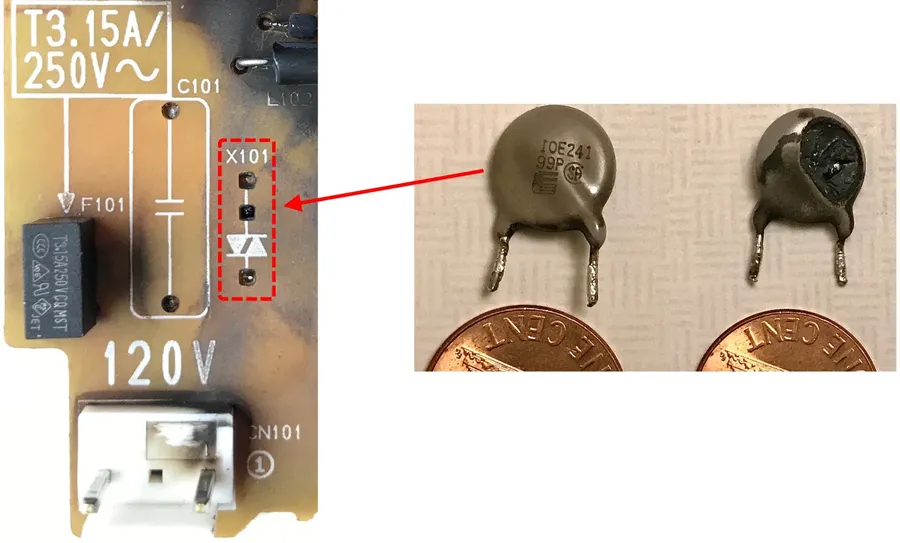
For a more comprehensive test, use a variable DC power supply. Gradually increase the voltage across the varistor while monitoring the current. The varistor should initially show very low current flow. Once the clamping voltage is reached, there will be a sharp increase in current as it starts to conduct significantly. Note this clamping voltage and compare to specifications. - Visual Inspection
Closely examine the varistor for physical damage such as cracks, burn marks, or discoloration. Such visual evidence often suggests internal damage or overheating.
Common Varistor Failure Modes include short circuits (very low resistance, often caused by repeated surge exposure or exceeding specifications), open circuits (infinite resistance, often from severe overvoltage events or physical disconnection), degradation (increased leakage current, caused by repeated surge events or time), and physical damage (cracks or burn marks). Each of these failure modes results in the component no longer performing as designed, reducing circuit protection or causing malfunction. It's important to conduct thorough testing as detailed to ensure optimal functionality of your protection components.
Frequently Asked Questions About Varistors
This section addresses common questions about varistors, providing clear and concise answers to enhance your understanding of these critical surge protection devices. We aim to clarify their behavior, differences from other components, and practical testing methods.
- What happens when a varistor fails?
When a varistor fails, it typically does so in one of two ways: it either becomes a short circuit, or it becomes an open circuit. A short circuit failure means the varistor's resistance becomes extremely low, potentially causing excessive current flow and further damage to the circuit if not properly protected. An open circuit failure means the varistor no longer conducts electricity, rendering it ineffective for surge protection. This often happens when exposed to a transient surge beyond its energy absorption capability, such as a lightning strike. In addition, repeated surges can degrade the varistor's performance over time, reducing its clamping voltage or increase its resistance. The failure mode depends on the specific varistor material, the surge conditions and circuit configuration. - What is the difference between a fuse and a varistor?
A fuse is an overcurrent protection device that protects a circuit by interrupting the current flow when it exceeds a certain threshold by melting a fusible element. A varistor, on the other hand, is a voltage-dependent resistor that shunts excess voltage to protect against transient voltage surges. Fuses protect against sustained overcurrent conditions, while varistors protect against short-duration voltage spikes. Fuses act as a one-time protection device and need replacement when activated, while varistors can handle multiple surges, albeit with a gradual degradation. In summary, fuses and varistors protect against different electrical faults; it is common practice to use them together to provide more comprehensive protection to electronic circuits. - Are varistors AC or DC?
Varistors are primarily designed to respond to voltage, regardless of polarity, and therefore, can be used in both AC and DC circuits. However, the voltage rating of the varistor must be appropriately selected for the specific application. For AC circuits, one must consider the peak voltage, not just the RMS voltage. In DC circuits, the steady-state DC voltage is considered for selection. The varistor's key performance parameter that must be selected carefully is its clamping voltage, which determines at which voltage level it starts to conduct. - How do you check if a varistor is working?
A basic check can be done using a multimeter set to the resistance (Ohm) setting. An intact varistor will exhibit a very high resistance (often in the megaohms range) at its rated voltage. A low resistance reading indicates a short circuit. An infinite resistance reading, while less obvious, indicates that the varistor is open. However, these checks are not foolproof and can only detect gross failures; more accurate testing would involve applying a voltage source and observing its clamping behavior which is generally performed out of circuit with specific test equipment. Additionally, the visual inspection of a varistor can provide clues: burnt or cracked components might indicate a failed device. - What is the 'clamping voltage' of a varistor?
The clamping voltage of a varistor is the voltage level at which the varistor begins to significantly reduce its resistance and conduct current. It's the point where the varistor effectively 'clamps' the voltage, diverting excess energy away from sensitive downstream components. This voltage is higher than the normal operating voltage of the circuit and the varistor must start to conduct before the downstream components see excessive voltages. The lower the clamping voltage, the better the varistor will protect. The clamping voltage should also be considered with the maximum allowed voltage of the protected circuit, to allow the varistor to perform its function correctly and without causing overvoltage damage to sensitive components. - What is the energy absorption capacity of a varistor?
The energy absorption capacity of a varistor, usually expressed in joules, indicates the amount of energy a varistor can safely dissipate during a surge event. This parameter determines its ability to handle transient voltage surges without failing, and it’s critical in selecting the appropriate varistor for a specific application. If the amount of energy in a surge exceeds the varistor's capacity, it can lead to degradation or catastrophic failure. The varistor's surge current and surge energy absorption specifications should be matched carefully with the conditions that are expected in a given application. The higher the energy capacity, the more robust the varistor will be against surges. - How does a varistor respond to repeated surges?
Varistors can handle multiple surges, but their performance may degrade over time with repeated exposure. Each surge causes a small amount of degradation, incrementally increasing the clamping voltage or resistance. Eventually, this degradation can lead to the varistor becoming less effective, failing or even short-circuiting. It is important to consider the varistor's derating requirements in repeated surge applications. It is essential to select a varistor with enough margin above the expected operational range to account for degradation and maintain performance over the device's lifespan.
Varistor Failure Modes and Replacement

Varistors, while robust, are not immune to failure. Understanding their common failure modes is crucial for maintaining the integrity of surge protection circuits. These failures typically manifest as degradation, shorts, or opens, each requiring specific identification and replacement procedures to ensure continued protection against voltage transients.
- Degradation:
Varistor degradation is a gradual decline in performance due to repeated exposure to surge events, even those below the maximum rating. This manifests as a decrease in clamping voltage and an increase in leakage current. While not an immediate failure, it reduces the varistor's effectiveness and should be monitored by periodic testing. - Short Circuit:
A short circuit failure occurs when the varistor's internal structure is damaged beyond its capacity to recover. This typically happens when a surge exceeds the varistor's maximum surge current or energy absorption rating. A shorted varistor essentially becomes a low-resistance path, and will not shunt excess current or provide protection. The symptoms may include excessive heat, a blown fuse, or tripped circuit breaker in the circuit that the varistor is protecting. - Open Circuit:
An open circuit failure results from severe damage to the varistor, where its internal connections are broken. This could result from a severe or prolonged overload, or by exceeding the varistor's life cycle. An open varistor is equivalent to a missing component, which renders the surge protection function completely non-functional. The protected circuit is vulnerable to damage from voltage spikes. The damaged varistor may also show signs of physical damage, such as cracks, discoloration or charring.
Identifying a failed varistor requires careful observation and testing.
- Visual Inspection:
Check for signs of physical damage such as cracks, charring, or swelling. These are strong indications of failure. - Continuity Test:
Use a multimeter in continuity mode to check if the varistor is shorted (near zero resistance). An open circuit (infinite resistance) indicates failure as well. However, note that most varistors show high resistance under normal operating conditions so they will show as an open circuit unless a high voltage is applied to the component. - In-Circuit Measurement:
When a varistor is degraded, it’s clamping voltage will be reduced. Although, this is difficult to measure in-circuit. This may show an increase in leakage current. For the most part, testing needs to be completed out-of-circuit using a DC power supply and multimeter.
When replacing a varistor, ensure the new component matches the specifications of the original one. This includes voltage rating, clamping voltage, surge current capacity, and energy absorption capability. Using a varistor with incorrect specifications can lead to inadequate surge protection or further circuit damage. Note that if a varistor has failed, there may be an underlying circuit fault that needs to be addressed before re-energizing the circuit.
- Replacement Steps:
1. Power Down: Disconnect power from the circuit. 2. Desolder: Carefully desolder the failed varistor. 3. Install New Varistor: Ensure proper orientation and solder the new component in place. 4. Test: Re-energize the circuit and verify proper operation. Do not touch live circuits. The best method of testing will be with a DC power supply and a multimeter as detailed in the section 'Testing and Troubleshooting Varistors'. - Safety Precautions:
Always disconnect power from the circuit before performing any work. Use appropriate safety equipment such as insulated tools, safety glasses and gloves. Be aware of the hazards of working with live circuits or electronic components. If you do not have appropriate experience or expertise, consult a qualified technician.
Future of Varistors: Trends and Innovations
The field of varistor technology is continuously evolving, driven by the increasing demands for enhanced surge protection in modern electronic systems. Future innovations are focused on improving performance, miniaturization, and reliability to meet the challenges posed by emerging applications and markets.
- Performance Enhancements
Ongoing research is focused on developing varistor materials with higher energy absorption capabilities, lower clamping voltages, and faster response times. This includes exploring new metal oxides and doping techniques to optimize the non-linear resistance characteristics. - Miniaturization
Driven by the demand for smaller electronic devices, there's a strong trend towards miniaturizing varistors while maintaining or improving performance. This includes the development of multilayer varistors and thin-film technologies which allow for higher component density and reduced form factors. - Reliability Improvement
Research is being conducted to address issues such as degradation over time and failure modes of varistors under extreme conditions. This includes improving the material stability and structural integrity of varistors to extend their service life and overall robustness. - Smart Varistors
The development of 'smart varistors' is an emerging trend, incorporating features like self-monitoring and diagnostics for performance evaluation. These devices may integrate microcontrollers or sensors to provide real-time status of their health, and provide more sophisticated control of surge conditions.
In terms of emerging applications, varistors are being increasingly utilized in the following fields:
- Automotive Electronics
As electric vehicles and advanced driver-assistance systems (ADAS) become more prevalent, varistors are critical for protecting sensitive electronics from voltage transients in harsh operating environments. - Renewable Energy Systems
Varistors are increasingly used in solar inverters and wind turbines to protect power electronics from surges due to grid disturbances and lightning strikes. - Smart Grids
With the advent of smart grids, varistors are critical in protecting smart meters and grid communication devices that can be affected by transient surges. - 5G and IoT Devices
The proliferation of 5G communication networks and Internet of Things (IoT) devices necessitates robust surge protection, making varistors essential components to safeguard data processing and transmission electronics.
The future of varistors also involves addressing environmental concerns. The focus will shift towards developing more environmentally friendly materials and manufacturing processes. In summary, varistors remain a vital and evolving component of modern electronic systems, with continuous research and development aimed at improving their performance, reliability, and sustainability.
Varistors are an essential yet often overlooked component in our modern electronic world, providing reliable protection against voltage surges. Understanding their function, types, and selection criteria is crucial for safeguarding our devices. As technology advances, the importance of varistors in ensuring the longevity and reliability of our electronics will only grow. By incorporating them thoughtfully into our electrical designs we can safeguard our technological investments from the unpredictable nature of power surges. This article empowers users to better understand varistors, and thereby contribute to building more robust and resilient electronic systems.